To do anything interesting, we need reliable communication across machines (e.g. over bluetooth) and oftentimes within as well, between components working together within a device. In one of my last projects, I wound up dealing with mounds of unreliable comm and here I’ll go over how I got around it and a few of the lessons learned.
The main issues addressed are:
- sending data over long lines (physically long wiring);
- ensuring masters and slaves are coordinated; and
- ensuring data integrity
The Project
The project was interesting in itself…
Wireless is great but the downsides include overhead dealing with all those layers and cost–when you’re adding a wifi chip to every module, it can add up quickly. Another big advantage of wiring everything together is, as in the case described here, that you can avoid providing power sources for a whole bunch of distinct units and simply add power distribution to your wired system (as in PoE).
In this case, the goals were to have a module:
- that had up to six remote sensor units, from which it would be gathering data;
- that could be connected to a desktop computer, via USB;and
- that would also be able to daisy chain other similar devices, and coral all that USB-level comm back and forth between the desktop user and modules behind it in the daisy chain.
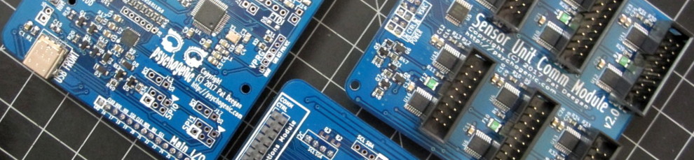
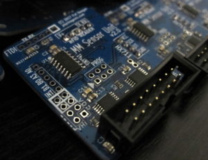
So everything would be acting as a single device, all wired together, with some of these wires extending several feet. This is the result

A central unit (combining stacked PCBs) and a bunch of little sensors to be wired into the “comm module” on the top, above.
Sensor Units: long distance SPI
 The sensor units are responsible for managing whatever types of sensors they’ve got on-board (RFID, load cells and other things) and all act as slaves of their parent collector device.
There are a few standard ways of interacting with slave devices, my faves being I2C and SPI. I2C is great in many cases, but the way it uses the communication line (with master and slaves sharing control by pulling it low) doesn’t lend itself too well to superlongwires.
SPI, on the other hand, is a pretty natural fit. Even so, if you try to do standard SPI over wiring that’s five feet long, driving lines directly from the pins on your MCUs you’re in for a bad time.
There’s the resistance of the wiring that’s proportional to it’s length so you wind-up trying to send your square waves through a nice RC filter, and you’ll probably hit weird interference effects between your own wires but most important is the fact that you’re basically placing a big antenna on the pins of your microcontroller.
At best, you’ll get signal degradation and worst you’ll happen to be at some node or anti-node of a bothersome radio wave, and now your pin is fried. boo.
The solution to most of these problems is pretty easy: differential signaling.
Instead of trying to maintain some specific voltage over our long wires to indicate our 1s and 0s, we send down a differential signal which indicates the logical state using the difference between the two. That way, the absolute values on the wires can jiggle up and down all they like because of interference from space, since both wires are sensibly traveling the same path, their common jiggles are ignored and what we’re trying to say actually gets through.
Using differential transceivers, say the MAX3030 and the like, has the added benefit that these guys are designed with this application in mind, so they can handle being connected to what is, in essence, an antenna so they have decent ESD protection built-in and your microcontroller is kept nice and safe. The main downsides of this approach are:
- the extra hardware on your board, and associated cost; and
- the extra wiring it implies (two wires for each signal line)
So now you’ve put in some RS-422 transceivers in your project and it works nicely over 6 inches. You may have a bit more work to do, though, especially if you’re using cheaper cabling (for instance, here I wanted to forgo the expense and trouble of dealing with twisted pairs and settled on flat ribbon cable). The good news is, the rest of the work is all algorithmic, so it can be handled without changing anything in your layout.
VNC2: The Battle Against Crappy SPI
Which brings us to the Vinculum II. Though a bit long-in-tooth, on paper the FTDI Vinculum II looks like a great solution whenever it comes to dealing with old-school USB.
It has two USB ports, which can act either as USB devices (peripherals) or USB hosts, which isn’t all that common, and it supports being an SPI master or slave. Sounds good.
The main problem with the VNC2 is that it runs some kind of R.P.O.S. (no, the ‘P’ isn’t a typo, it really is a PoS).
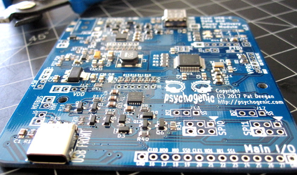
So I design and fab a couple of these boards, built around the VNC2 with comm going over legacy USB D+/D- and USB-C stuff in the mix so I can deal with Power Delivery and actually provide power to my entire daisy chain from a single device. Neat.
Then I move into coding for the thing. worst. time. ever.
First off, I have to find some Windows machine, because it’s proprietary blah and you have to use blah. Also, you’re restricted to a subset of C. Agh, ok fine. The IDE dates back to windows 3.1 or something, is painfully slow, allows for all of 3 breakpoints, continually forgets your settings, re-enables breakpoints you disabled and is generally hellish.
Though there are some examples for a lot of typical uses, most of them are toy code and don’t do anything serious (e.g. the SPI slave examples will read some data, but are completely silent, you never once see anything talk back). Worse, the documentation has giant black holes everywhere (“vos_init() takes three parameters… two of which, well, probably impact things in ways” or “oh yeah, footnote: if you want to talk to anything that isn’t another VNC over SPI, you must use ‘unmanaged mode’ though we won’t actually tell you anything at all about the difference, anywhere on the whole internet“).
Anyway, I manage to create firmware that has three threads going:
- USB peripheral
- USB host
- SPI slave
Seems to work fine, until I actually start using the SPI. Without going into details about the struggle, the SPI:
- gets woefully sluggish as soon as the device is actually plugged into a USB port (even if there’s no actual activity)
- seems to drop bytes you are sending it, depending on how busy it’s doing whatever, even though you’re supposedly using buffers
- when the VNC is transmitting data over SPI, will repeat most–but NOT ALL, just most!–bytes twice
Whaaaat?
Those sensor units we covered above? They run exactly 6 times slower on minuscule ATTiny841s and never exhibit any of these horrors.
The worst of them was the (almost constant) repetition of the bytes transmitted through SPI. I contacted FTDI and they, after a few days, finally said “yes, yes, the VNC2 is still supported but maybe you should use this other chip” with 0 assistance, advice or word on the troubles I was dealing with.
The short story is that after much mucking about, I have determined that I was going too fast for the poor thing. I slowed down SPI communication as far as I could go–dividing the XMEGA 32MHz clock by 128 for a whopping 250kHz clock–and it was still too fast. It’s like I was requesting the next byte before the VNC’s buffer index was incremented, so it was just repeating the last thing out. Most of the time, that is.
The solution for this was to slooooow the SPI clock signal further still, by implementing a bit-banged SPI protocol manually and slowing the clock to… drumroll… 10kHz. Yack.
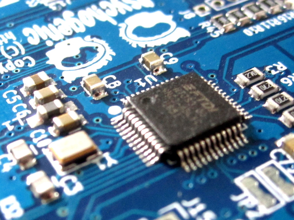
The culprit: Vinculum II
But the problems didn’t end there, because SPI is all about being synchronized. If you’re sending dummy bytes on your MOSI line, expecting to be receiving a stream of data, the other side had best be ready with the outgoing data, or you’ll be reading junk.
With many chips, this often means the master sending something like:
GIVE ME REGISTER XYZ (I’m expecting 2 bytes of data, say)
HERE’S A DUMMY BYTE (to give you a moment to prep)
CLOCK 1 BYTE for D0 (get the first byte)
CLOCK 1 BYTE for D1 (get the second byte)
horray, we’re done.
In this case, the VNC2 crappy SPI was being caused by the RPOS so sometimes it’d work, sometimes it was busy elsewhere.
Best case: request simply dropped, disappearing into the aether.
Worst case: get the request, go to the fridge for a snack while the master is piping in junk data, come back and prep your outgoing data, sit there waiting for the master to eat it, mess up the next request because you still think you’re transmitting old data, hilarity ensues.
Coordination: Getting Around Crappy SPI
What’s needed to get around this type of unreliability is a way to ensure we’re all on the same page. This only applies if you’re controlling both sides of the equation–if you’re using someone else’s SPI protocol, well that’s that.
But if, like here, you’re designing both the SPI master and its slaves, then you can do what TCP does for IP: implement a layer above the simple byte-level transmission level to ensure synchronization and reliability.
I won’t get into all the details, but the gist of it is:
- a SYN/ACK system
- a checksum for validation
All SPI comm comes down to messages from that master that involve:
- “Give me some data that you have”;
- “Accept some data that I am sending you”; or
- both at the same time, if you want to get fancy.
So the first phase is, as the master, to tell the slave what you want (in essence issuing some command) and then to get it done.
Reliable SPI: implementation
If you’ve got a slave that’s either slow or otherwise unreliable, you can use a system like the one I created:
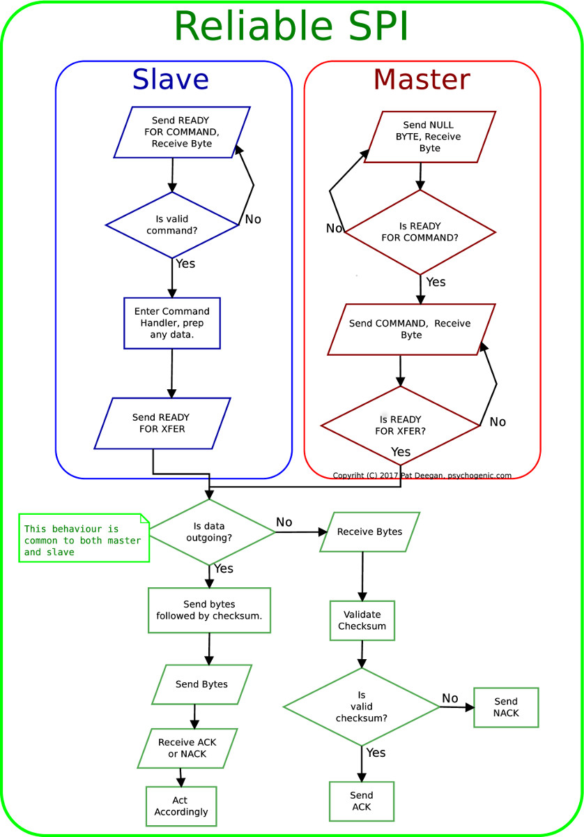
Though, in reality, I’ve used extra bits to implement things like a hardware interrupt flag through a pin, and message headers to define the length of transmitted data with their own checksums etc, this shows a basic way to get synchronization without using delays or weird timing tricks plus crossing your fingers.
The slave tells the master it’s ready to go (using a special “READY FOR COMMAND” byte code), when the master sees this it issues it’s command. The slave may take some time at this point to get setup, all the while the master will be checking for the “READY FOR XFER” flag.
The slave that isn’t ready will be “transmitting” either zeros, or the last value it sent (the ready-for-command byte) or 0xFF or something else platform specific (just make sure it doesn’t collide with your ready for xfer byte).
The point is that when it’s ready to send or receive, the slave transmits the ready-for-transfer. Then we assume we can go at regular SPI speed for the agreed-upon number of bytes (be it pre-determined by the command, or a pre-determined message header that indicates payload size).
At the end of the op, the receiving end will validate the checksum and the roles reverse for one byte: the sender shoots off a dummy byte and the it’s the receiver’s turn to either send an ACK or a NACK byte. How this influences behaviour is up to you.
With all this, you can be pretty certain your messages are getting through.
The checksum itself is left as an exercise for the reader. Though you can get some value out of using more complex schemes, the checksum can be as simple as the result of XORing or simply adding all the bytes to be transmitted into a (possibly overflowing) single unsigned 8-bit value.
Conclusion
The ReliableSPI implementation was done for the horrid VNC2, and worked pretty well. Only “pretty well” because the fact is that though it says on the box that it supports 2 USB ports, and SPI and blahblah, it just doesn’t seem to be designed to do all of this at once.
The protocol does it’s job, but my MCU winds up repeating messages two to seven times before getting through. Combined with the slooooow SPI clock I need to use, this introduces too much lag for real world use in our application and I’m going to have to redesign my USB layer with some other IC… I hesitate to use the FTDI stuff, now, as the experience was bad and I got no love at all from the company when facing these issues.
Still, the ReliableSPI system has proven itself and, since it was already done, I added the functionality to the ATTiny-based sensor units, too, and it allows me to trust the data I’m getting while providing flexibility in the sense that the units can take whatever time they need. If, in the future, we have some type of sensor that requires more time to do it’s thing, no changes will be required on the master’s side and things will just keep working.
I hope the above shows how you can get by with the magic of wires, to let you use familiar SPI (with a few tweaks) to talk to interconnected devices and that it’ll help you in your own projects!