Before covering construction, I’ll go over ACID’s “theory of operation” and discuss how it all works.
Perception

TCS3200
The TCS3200, a programmable colour-to-frequency converter, is the small chip at the heart of the project. It functions much like the human eye, in that it has three sets of photoreceptors with peak sensitivities in the red, green and blue portions of the visible spectrum.
Unlike our eyes, the TCS3200 can only report on the state of a single photoreceptor type at a time. It does so using a train of pulses with a frequency proportional to the amount of incident light of that colour, scaled according to a configurable setting.
Another difference, implied by the TCS3200 datasheet but which caused some serious head-scratching until it was understood, is that infrared light must be kept out of the detector. Two things are worth noting from the responsivity curves of the photoreceptors:
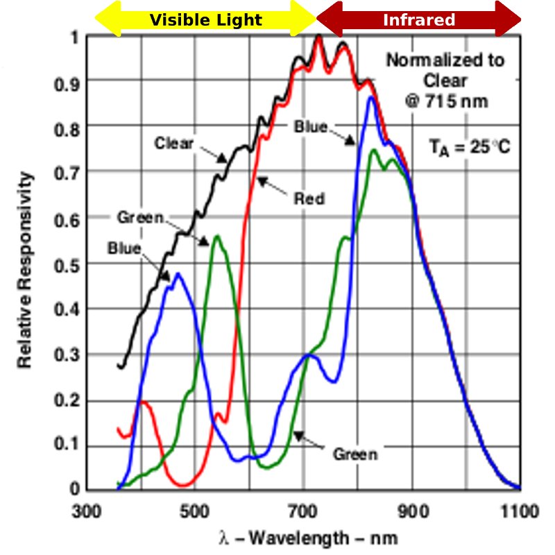
TCS3200 Responsivity Curves
First, the blue and green photodiodes react to light of the corresponding color (with a little overlap) and then again–and actually a good deal more–on the far right in the infrared region. The red photodiodes have a wide peak, that spans both visible and infrared light.
This means that, without an appropriate filter, the TCS3200 will scream “WHITE!” whenever there’s a source of IR around. Which is often. Really often.
The second thing to notice is that certain colours are more readily detected than others, as the sensors react more strongly to higher wavelength light.
The program accounts for the difference in responsivity for each colour, but there’s no software fix for IR interference: an IR filter is required. This is covered further, below.
Processing
Brain
 If the TCS3200 is the heart of the system, the brain is an Arduino microcontroller. The Arduino Uno was used during development but, for the sake of having something portable, it was important to have an Arduino with a smaller footprint.
I’ve covered the Ardweeny, based on Kimio Kosaka’s “One-Chip-Arduino” project and developed by Solarbotics, in a previous post. It is the one of the smallest Arduinos with through-hole components. Everything fits on the back of the ATmega328, so it only takes up as much room as the microcontroller itself, and it’s easy to build.
Though it’s true that the ‘mega and handful of supporting components could have been included directly on the mainboard, the ease of programming, versatility and reusability (when a socket is used) of the Ardweeny make it a favorite Arduino (compatible) in these parts.
The only downsides are the need to provide a source of power–easily done through the use of a low-dropout regulator–and the required FTDI programmer, which is a small USB board that slides onto the 6-pin header on the top to burn the program in the Mega.
Once you’ve used the Ardweeny, you’ll begin to find more and more places where it comes in very handy.
Mind
The best source of information concerning ACID’s mind–the program that runs on the Arduino–is the source code itself, but an overview will be helpful in establishing context prior to diving in to functions.
Though the frequencies involved aren’t excessively high, the program is centered around providing timely generation of the audio, as this is the primary input for the user. Along with a few interrupt service routines–that handle timing, sample counts and calibration button presses–the program follows this flow:
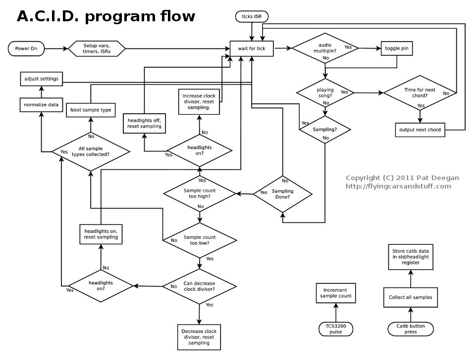
ACID Program Flow
The three tones used by ACID–C, E and G, forming the C major triad–need to be generated continuously and in a timely fashion in order to avoid straying off key or causing noticeable audible artifacts.
The frequencies selected are:
- C3 at 131Hz;
- E4 at 330 Hz, and;
- G5 at 784 Hz.
To generate these tones, we need only toggle an output pin at twice the desired frequency.
Using a single timer set to trigger an interrupt every 128 microseconds, and defining this interval as one clock tick, and by inverting the state of the
- C3 pin every 30 ticks,
- E4 pin every 12 ticks, and
- G5 pin every 5 ticks
each tone will be generated appropriately, with a good deal of accuracy.
In the first version of the device, each tone would pass through an amplifier with a digital potentiometer in the feedback loop, to allow gain adjustments. To simplify construction, and reduce the part count considerably, ACID was redesigned so that amplitude of the pulses for each tone would be set by software, using a “switched pwm” technique.
An analog output level is simulated using high frequency pulse width modulation, and the pin is switched between this pseudo-analog level and 0V at a rate corresponding to the tone frequency. After that, only a few passive filters are needed to smooth the tone outputs.

Low amplitude switched PWM tone
A higher amplitude tone of the same frequency is generated using the same technique, but with a higher “analog voltage” pulsed on and off–which actually looks like this, up close:
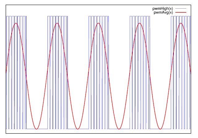
Higher amplitude tone, where micropulses have higher duty cycle.
Once everything is setup, every subsequent step happens during a single tick. In order to ensure that all the data processing can be done within a single 128 microsecond slice, the data processing of the recorded samples is split over a few ticks using a number of global state flags. With this in mind, exploring the actual source is definitely the best way to see all the details. The major components are:
- audio generation
- TCS3200 configuration and pulse accumulation
- control of the digital pot over SPI
- data processing, including responsivity adjustments, differential signal amplification and normalization
- “white balance” calibration, with EEPROM data for both bright lighting conditions and low lighting (headlights on)
- a simple song player, using the 3 notes at our disposal, for user feedback (power on, calib start/end)
Schematics
TCS3200 Control Module
The TCS3200 module allows the TCS3200 to be positioned at a right angle to the mainboard, and is an easy way to use the colour-to-frequency converter with other projects.
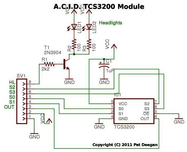
TCS3200 Module Schematic
The circuit is little more than a breakout for the TCS3200, along with a few optional LEDs–used as optional “headlights”–that are switched through transistor T1.
Main board
The main board holds the Ardweeny, supporting electronics and interconnects with various off-board components, such as switches and the TCS3200 board.
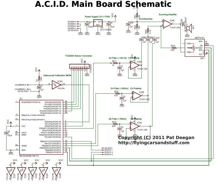
Main board schematic for A.C.I.D.
The circuit for the main board is relatively simple. The three audio tone pins are fed to their own low-pass filter, with values selected to have a cut-off frequency near the note’s frequency.
The tone is then buffered by an op-amp configured as a simple follower. Finally all three are merged using a fourth op-amp, setup as a summing amplifier. Within this summing amplifier’s feedback network, the digital potentiometer allows us to adjust the gain by programming its resistance over SPI.
An SPI header is included so the program may output data on each colour, whenever it has changed, for use by external circuitry.
Now that you know how it works, it’s time to build ACID.
Project Pages
ACID Overview
[siblings]