Go from HDL to physical CMOS layout right now with the help of this guide and some great open-source tools.
I’m currently following the Zero To ASIC course, which pretty much does what is says on the box: helping you learn how to move beyond the FPGA and get your hardware descriptions transformed into real integrated circuits. One of the parts I really like about this is the focus on open technologies and software, along with the SKY130 PDK.
After getting familiar with some basic concepts and tools, one of the first things I was eager to try was converting hardware descriptions, high-level and abstract, into physical layouts of MOSFETs and wiring as they would be integrated within a chip.
Walk-through and Demo
I’ve created a playlist which I’ll be filling with my ASIC-related discoveries, and included this discussion and walk-through. I had some fun making it and hope you’ll enjoy it:
Quick Start
You can give it a spin right now with a bit of setup and basically one command, thanks to a little Makefile I’ve put together (Note I’ve only played with this under Linux, if you can help try it out/make it happy for other operating systems, let me know).
- Install OpenLane according to it’s instructions. In short, it’s a clone of a repo, make and make test. I’ll assume it’s under ~/OpenLane
- Download a copy of my forked version of the TinyTapeout Verilog demo.
- Move that tt03-verilog-demo directory in the designs subdirectory of openlane,
mv tt03-verilog-demo* ~/OpenLane/designs - Get yourself into that directory,
cd ~/OpenLane/designs/tt03-verilog* - Finally, all you need is to
make gds
and it should just do it’s thing for a few minutes… When you see
[SUCCESS]: Flow complete.
you know it all worked out smashingly. That tt03* directory can then be used as a template for your own projects. Just stick the verilog *.v files under src/ and edit info.yaml to set
- the list of actual .v files being used in your project
- the name of the “top” module
and the make commands should just work. Note that the die area and other parameters are setup for use with TinyTapeout, which has some implications I’ll describe below.
The Makefile
The Makefile I created is just a handy way bundle a bunch of commands into one place. If you’re curious about how any one of them works, just issue the make with a “-n” flag, to do a dry run and print out the steps it would actually take.
For example, the klayout_cells target shows you the generated GDS file, using klayout in the openlane docker container, so running with the -n you can see all the footwork it’s doing to mount the project into the container and setup X
$ make -n klayout_cells

docker run -v /tmp/OpenLane:/openlane -v /tmp/OpenLane/pdks:/tmp/OpenLane/pdks \
   -v /tmp/OpenLane/designs/tt03-verilog-demo:/work \
   -e PDK_ROOT=/tmp/OpenLane/pdks  -e PDK=sky130A \
   -u 1000:1000 --net=host --env="DISPLAY" \
   -v /tmp/.X11-unix -v /tmp/.docker.xauth \
   -e XAUTHORITY=/tmp/.docker.xauth efabless/openlane \
	/bin/bash -c "klayout -l /work/.klayout-cellfocused.lyp \
         /work/runs/run0306/results/final/gds/*.gds"
Useful and interesting things you can do include
- make gds to run the flow on the project and convert verilog to layout and GDS ;
- make png to generate PNG (and SVG) images of the GDS;
- make info to spit out some project stats;
- make klayout_cells to explore the cells and routing in klayout;
- make show_latestdb to load the latest *.odb file in the OpenROAD GUI
and, when you want to play around in the openlane environment and do anything else, there’s
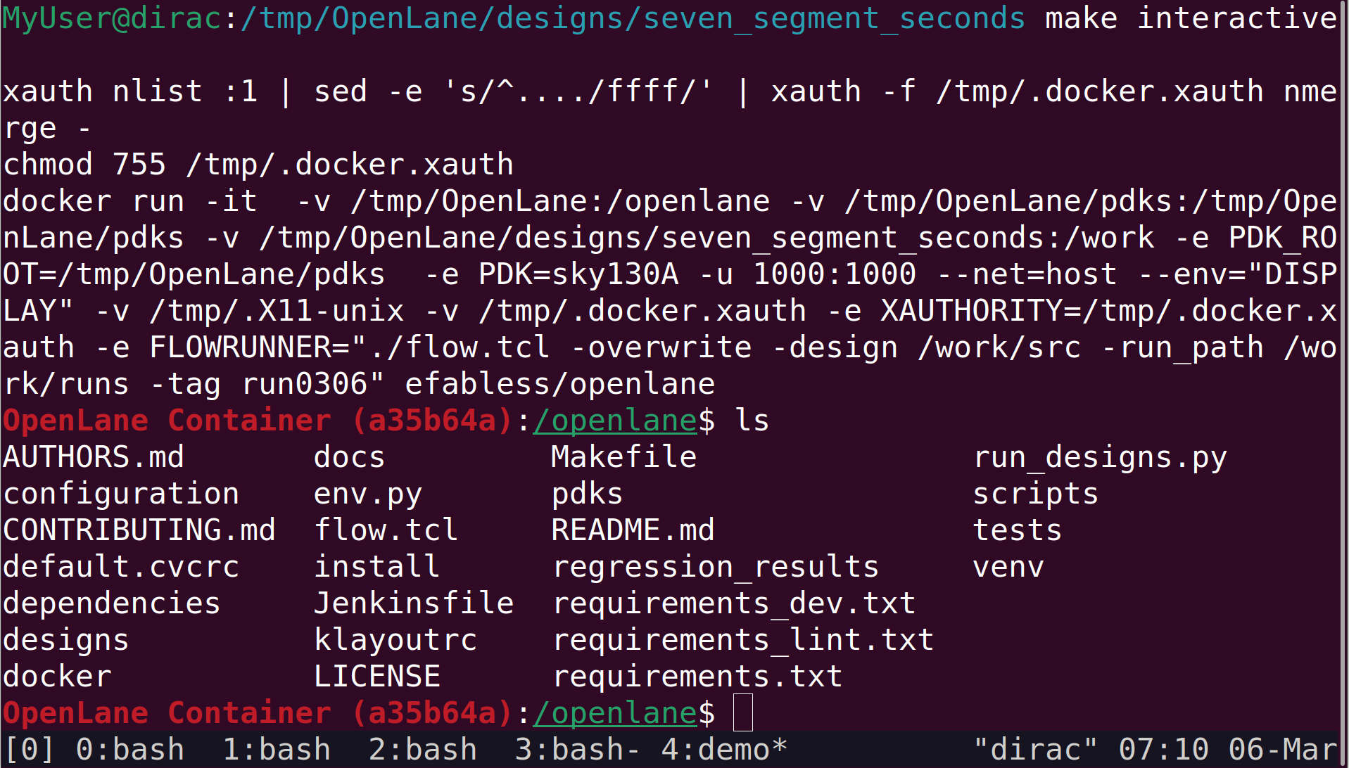
- make interactive
which gives you a shell with the current project directory mounted under /work.
Running the OpenLane Flow
Doing a
make gds
from within the project directory is all that’s needed in most cases. To try and balance out convenience and flexibility, this will generate a new run output/cache directory every day, calling it runMMDD (e.g. run0306 today, March 6th). If you want to override this, or refer to a pre-existing run, you can set an environment variable called FLOW_RUN_TAG or just prepend it to the make call:
FLOW_RUN_TAG=mytag make gds
which would be playing in runs/mytag instead of the default.
If you want control the process directly, start by getting access to the shell in the openlane docker container, in a way that gives you access to your project files. Use
make interactive
from within the project directory, and you’ll have everything under /work. But openlane has it’s own make mount and you can do that, too, if preferred, just adjust accordingly.
From within the docker shell, the flow.tcl script is available. To simply execute the flow manually, you can do something like
./flow.tcl -overwrite -design /work/src -run_path /work/runs -tag run0306
which passes in the directory for *.v source files (/work/src here), the parent directory for output (/work/runs) and the tag will the reference used for this particular run, as well as the name of the output directory under the -run_path (e.g. /work/runs/run0306).
You can also use the -it flag, to run the flow script interactively. But, as far as I can tell, we aren’t exactly drowning in documentation on this front and it’s pretty bare in there and you’ll need to sharpen your TCL. There are some samples in tests/ where you can learn to do steps like
% prep -overwrite -design /work/src -run_path /work/runs -tag sometag
and then use the various commands as defined in the various OpenLane/scripts/tcl_commands/*.tcl files.
Configuring the run
By far the easiest way to do things is to use make gds or the use the ./flow.tcl call as described above, and let openlane handle everything. But you still want to be able to control things.
That can be accomplished by setting up environmental variables in the src/config.tcl file. Note, if you are doing this to take part in the actual Tiny Tapeout, you can’t change anything in there. Each project in the set gets the same settings.
But if you’re exploring or rolling your own, config.tcl is where its at.
There are lots of variables to play with, though for the most part the defaults are great. For some reason, I always have trouble finding the documentation for these things, so I suggest an immediate bookmark to this page of OpenLane configuration variables documentation.
The variables are sensibly named, with many of them having prefixes related to the step in the flow to which they apply, like PL_* for placement, CTS_* for clock tree synthesis, GLB_RT_* for global routing, etc.
I’m going to document a few of these separately, but for your runs the most immediately useful may be
- DIE_AREA
- PL_TARGET_DENSITY and
- SYNTH_STRATEGY
DIE_AREA is pretty obvious. Short version, if FP_SIZING is absolute, then this this the die area as a rectangle from corner (x0,y0) to (x1,y1), in micrometers. If you are using a more complex digital design that isn’t going to be submitted to tinytapeout, it’s likely the default DIE_AREA may be a bit too small… just edit this.
PL_TARGET_DENSITY is how tightly packed you want placement to be (value between ]0.0, 1.0]). Tighter (closer to 1.0) is smaller, but harder to route. Default is 0.55 and there doesn’t seem to be tons of headroom above that.
SYNTH_STRATEGY is an interesting one, a basically points the system towards what kind of tradeoffs you want to make, what you priorities are (i.e. speed or area). Check the docs.
Exploring the Results
If you’ve gone through the flow and have successfully produced GDS output for a design, or even if its only a partial success, you can easily have a peek at what things are looking like in 3 ways.
Images
If the GDS was produced, you can generate SVG and PNG images of the die with
make png
which will, after a bit, spit out gds_render.png and gds_render.svg.
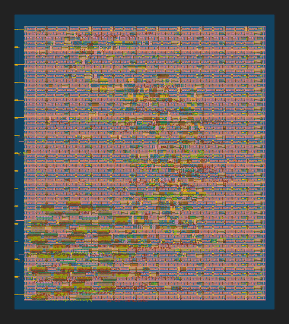
The PNG isn’t super high res, but it’s a good way to get an overview. Inkscape is good to look at and edit the SVG, but it’s a heavy file.
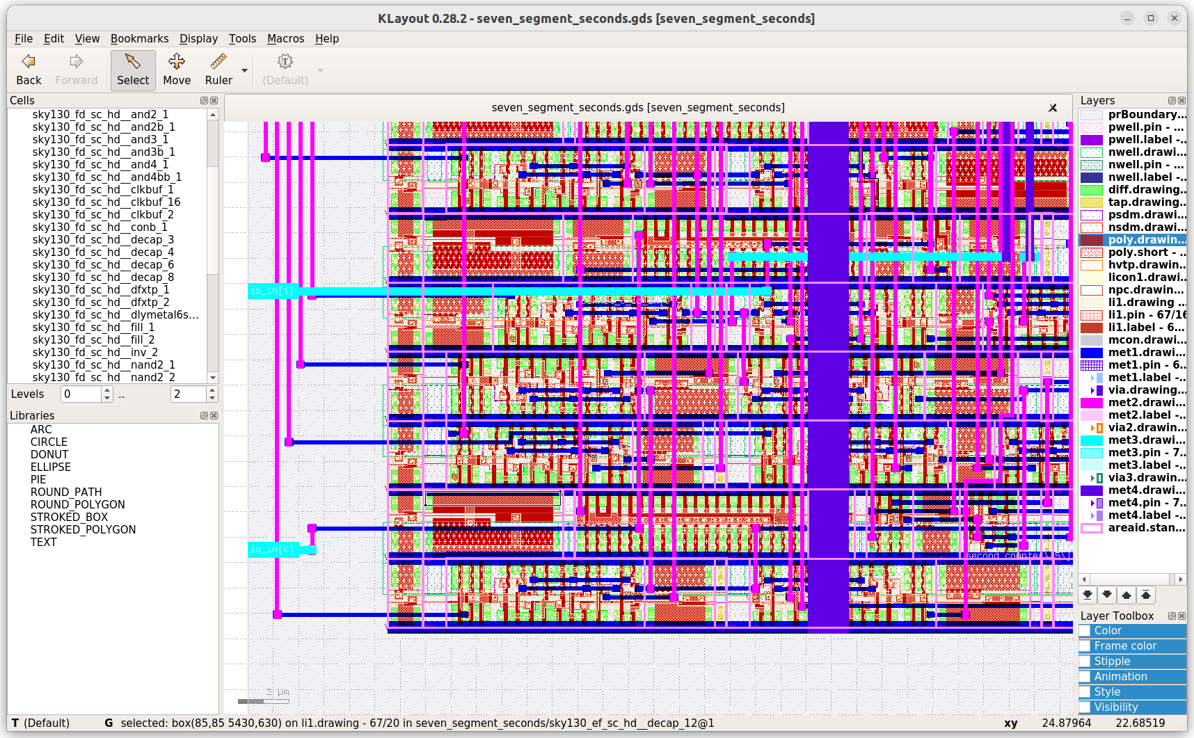
Klayout
Klayout is a very sweet program (if you’ve played with magic, then very very sweet program) that lets you view and edit, as well as script and generate or search and analyze, GDS files. It’s bundled with openlane, and my Makefile has a target that makes loading up your layout along with the layers config etc nice and easy:
make klayout_cells
This will open up klayout but, if this is your first use of it, it can be a bit weird to get around so do check out that part of the walk-through video above.
OpenROAD
OpenROAD’s main concern is running the flow and producing reports but you can run it on the console or as a graphical interface.
If, after getting access to the openlane shell as described above, you launch openroad, you’ll have access to the internals in a way that’s a whole lot friendlier than in the flow.tcl script.
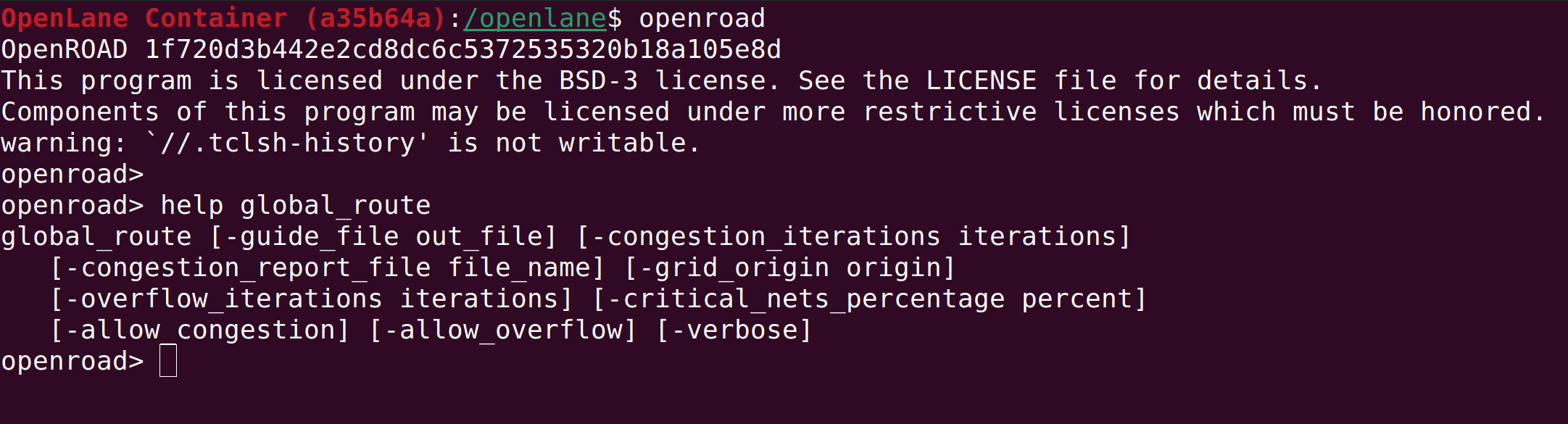
For viewing a graphical representation of the layout, heatmaps for routing and placement and more, the GUI is pretty nice. You can launch that from within the shell using
openroad -gui
or, you can automatically launch the openlane shell, and the openroad GUI, while loading in the latest *.odb file for the run, by using my Makefile (in the project directory) and doing
make show_latestdb
which will load everything up and give you something like
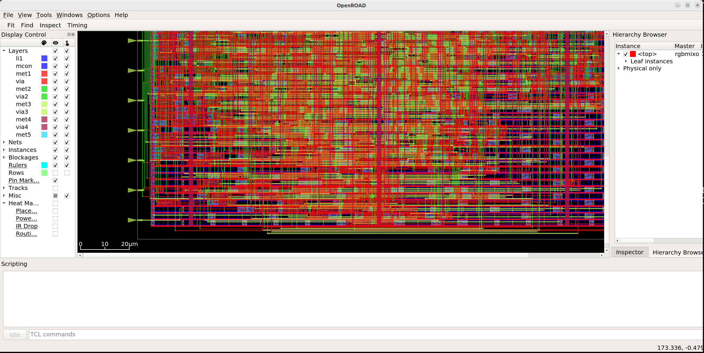
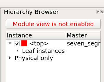
I was wondering how to view the cell internals at some point in the video. Answering my own question, I think I’ve found that you can close the timing dialog on the right side, then you’ll see the “Hierarchy Browser” and it has this “Module view is not enabled”. That’s a button. Click it, and everything loads. Hurray.
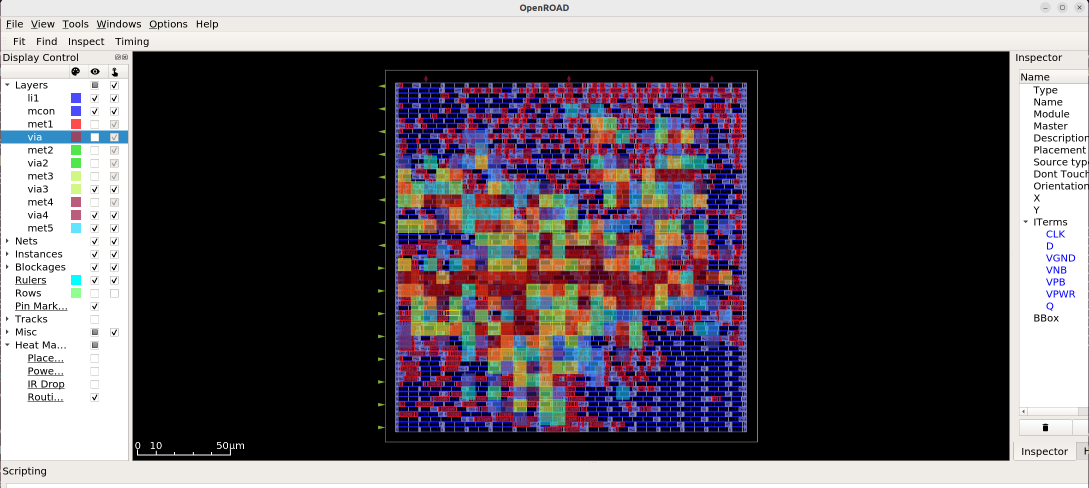
You can then find and view specific cells in your design.

The “Heat Map” options on the bottom left allow you to place heat map overlays, for routing etc. The dialog to set options for a given heat map is in the menu, under Tools -> Heat Maps.
TinyTapeout
The template project works with the assumption that the design will be embedded in a TinyTapeout. TinyTapeout deals with lots of stuff for you as it allows you to join in the MPW. It will give you 16 I/O, 8 input and 8 output. To get it all working, you basically just need:
- To setup your project within the template structure;
- Have a top module that has a distinct name (not just ‘top’); and
- That top module needs to have io_in and io_out that the rest of the system can tie into.
You can check the example verilog, but in essence it boils down to using something like
module my_top_module (
    input [7:0] io_in,
    output [7:0] io_out
    );

    wire clk = io_in[0];
    wire reset = io_in[1];
Moving forward
I hope this template/Makefile/info was useful to you and that you’ll play along with creating designs and maybe submitting them for inclusion into TinyTapeout too.
I’ll soon be getting into the details of actually creating these designs, rather than simply translating existing designs into hardware, so stay tuned for that. In the meantime, please don’t hesistate if you have any questions or comments–send them to me, or post them on the video.
Cheers!