
This is a complete guide to how I create and use 3d printed feeder sets for cut tape components in a pick and place machine.
With many low cost pick and place machines, like the LitePlacer I have, you can just stick the tapes to the work surface and get going. But I find this messy and, more importantly, less than ideal because of the extra hassle in configuring and refilling parts between batches.
Here I’ll touch on how to customize and print up these nifty trays which hold sets of cut tape feeders together, how to configure them for use with OpenPnP and how to use them effectively in your installation.
I also uploaded a video which goes over some of this as part of actual assembly project, where I had to generate a few new feedsets, so you can see the entire process in live action.
Here I’ll go over some of the things I didn’t get too deep into, and provide extra info.
Generating and printing
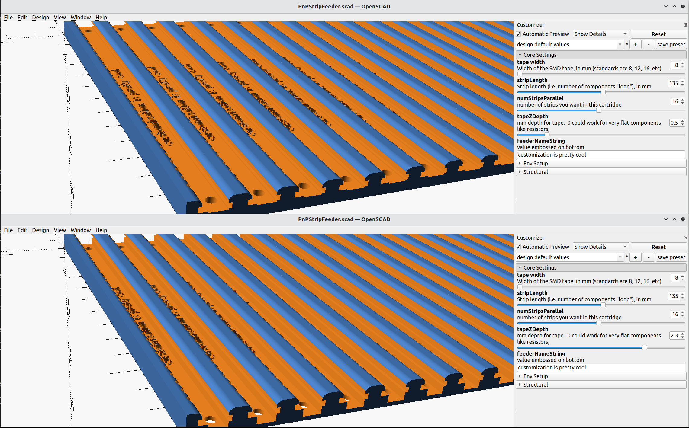
The OpenSCAD script is available for download on the thingiverse, along with a couple of example feedset STLs.
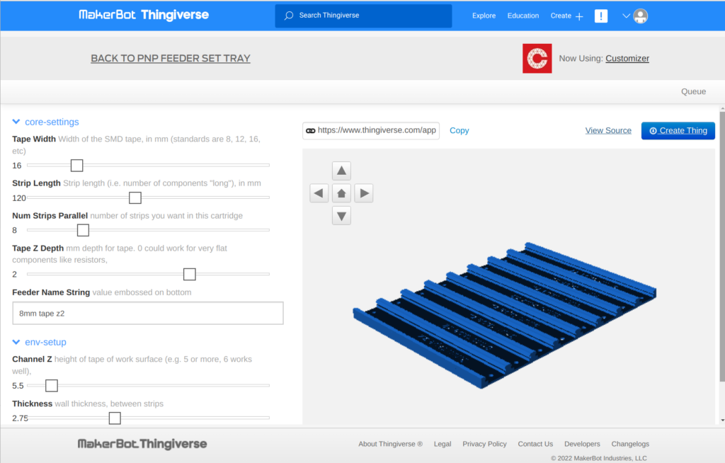
Though you can use the thingiverse customizer and it (usually) works, it’s a bit finicky sometimes and I’d rather do things locally anyway. So, to customize the feeder sets, I use OpenSCAD directly.
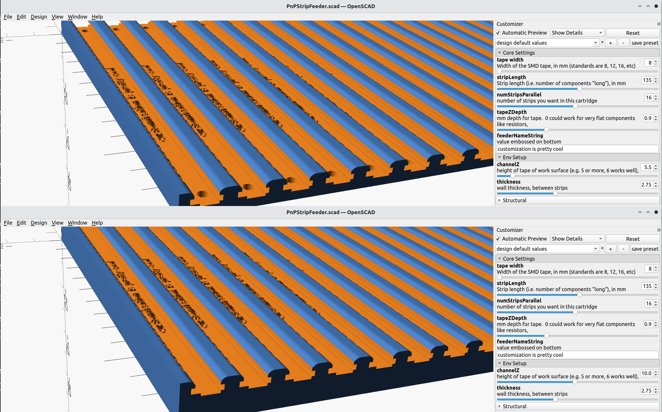
You can dive into the source and edit variables directly, or just use the nice built-in customizer, which is more than flexible enough in almost every case for me.
When you start using these trays, it’s wise to settle on some standard dimensions that make sense in your setup and keep re-using those. Some of these are pretty fundamental, are determined once and pretty hard-set. Others are matters of convenience.
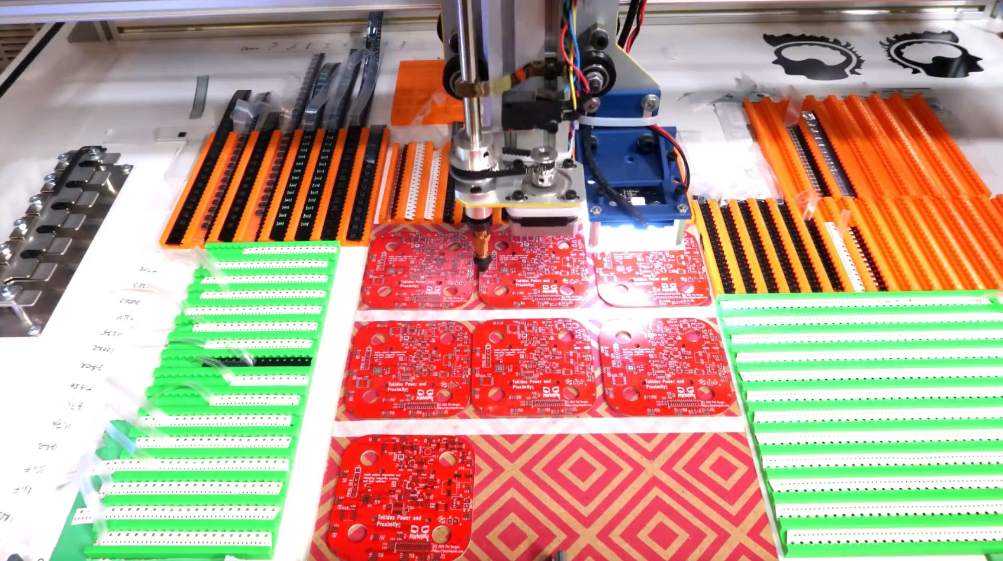
The trickiest of the bunch is the height at which the tape winds up, in the tray. Ideally, this will be exactly the same as the top of the PCBs being populated. Here’s my setup, and though they are precisely at the same height, this is more than good enough.
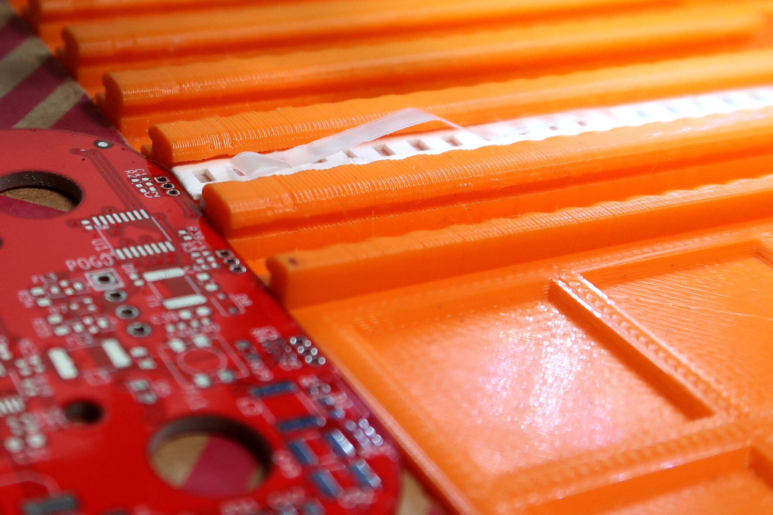
You may have noticed that noisy pattern under the PCBs. I’ve actually got a number of these and they’re just the backing from some dollar store clipboards. They’re stiff and thick enough to raise the PCBs a bit, and they are mate and dark enough that the auto exposure adjustment doesn’t have a bad time when looking for fiducials at the edges of my boards.
I also sometimes use these as trays for batches of solder-pasted boards, and I’ll create grids or alignment marks with masking tape to save on some work when resetting the origin of the PCBs in new runs.
The point is that this allows the PCBs to be at the same height as the tapes, while giving the feeder sets enough vertical height to allow for rigidity and some flexibility in the component channel depth. In my case, that’s using 5.5mm for the “channelZ” (available in the customizer in the “Env Setup” group).
Note that this number isn’t super obvious—the bottom of the tape will be about 2.25mm below whatever value you set (so in my case, with it set to 5.5, the cut tape floats about 3.25mm above the surface), so 2.5mm is about the smallest possible value and would likely be hard to print.
Once you have your preferred channel Z, I recommend you edit the scad script source so it always defaults to the correct value.
Once you’ve figured out your channel Z, the rest is all pretty much a matter of preference. For each feed set for a particular tape width, you get to choose the number of feeders and their length and the depth of the channel for accommodating thick components.
You could have a whole bunch of different feedsets for specific use, but I’ve settled on a few standard values. For instance, 8mm cut tape is extremely popular for the components I use most, so I have a number of 8mm feed sets.
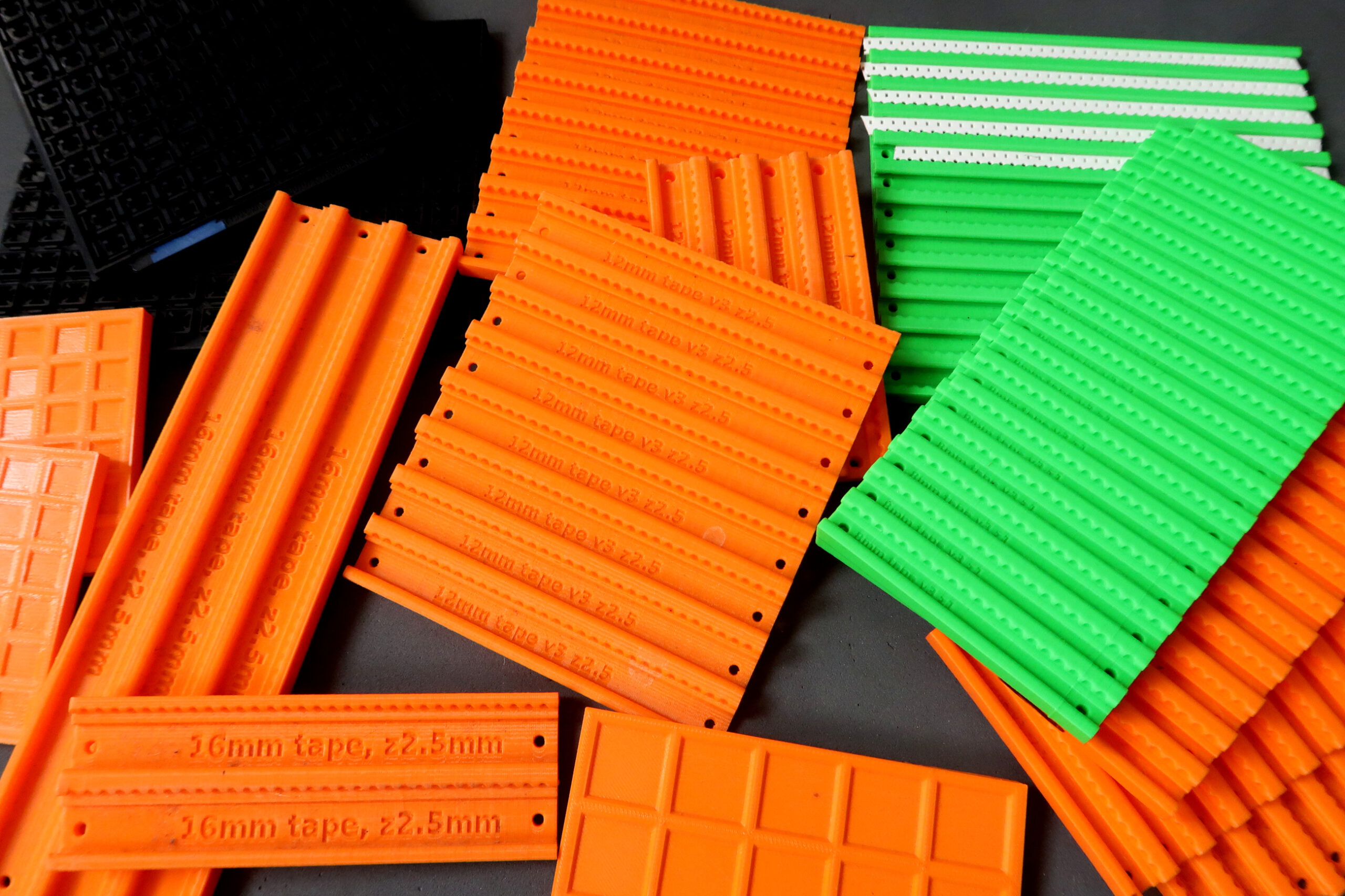
To simplify my setup and make the physical objects interchangeable, I use two different package types:
- small—16x8mm feeders 85mm long—which is great for low-count components; and
- long—12x8mm feeders 160mm long—enough to accommodate 80 0402s or 40 0603s in a single feeder row.
For the small sets, I have a selection of different tape Z depths, which allows for sets that handle fat components, like larger value 1210 caps, as well as flatter versions. This is setup using the “tapeZDepth” setting in the customizer.
The advantage of using deep feeds, say 1 or 2mm, is that they accept pretty much anything in 8mm tape. The downside is the need to be more precise with how far down the pick and place head will go when picking up the component—too far and you increase the risk of bouncing the tape around and winding up with a sad mess to clean up.
Since the long feed sets are mostly useful for very high-count components, and these are pretty much always just capacitors and maybe some pull-up or jumper resistors, I give these a minuscule depth of 0.7mm which minimizes bounce even if I’m lazy with the pickup config but is still enough to handle a variety of components like SOT-23 packages.
For other sized tapes, like 12mm and 16mm, I’ll have less feeds in the set and usually longer tapes. I’ve gotten by with a couple of 3x16mm and 8x12mm… I mostly use small parts, it seems.
Once you’ve generated your feed sets and have STLs, it’s just a matter of printing them up. If you don’t have a 3d printer, there are services like treatstock that connect you with some pretty cool folks that can do it for you. Either way, the main thing to note is that, when viewed as they’ll be used—i.e. sitting on a table—there’s some pretty important overhang. The solution here is to print them standing up on their side. This hasn’t been an issue for my 3d guys, but it does limit the length of the feedsets to however much Z the printers have.
Because I always forget the particular direction with which the pnp will pick up the components, I use ye olde sharpie and stick an arrow on the underside of the trays to clear up confusion once and for all.
Configuration and use with OpenPnP
I’ll admit I haven’t updated Openpnp in a while, so things may have improved by now, but how I initially setup the feedsets is pretty raw. I basically have a little bash script which asks how many feeders are in the set, the base name for the collection and a template to use. It then does some search and replace for the feed id and name (id=”FDRID” name=”FDRNAME” in the template) and spits out a bunch of xml.
Each of the names are just BASENAME_NN, with NN going from 01 to 16 or whatever. Then I just paste that into machine.xml within the <feeders /> element. The end. Here’s an example, but the best thing would be for you to setup a feeder just how you like it, then go get it in machine.xml for use as your own template. Or you can just create them manually—uggh, no thanks.
From then on, launching OpenPnP shows me the set of feeds and I can position them as usual.
I’ll usually have a sets of the smaller 8mm trays arranged around the PCBs and named appropriately enough 8mmLeft_*, 8mmTop_* and 8mmRight_*. 12mm and 16mm sets usually wind up somewhere at the top or left, notably because these guys usually have bigger components, so less density and thus much longer, so I’ll have them extending passed the actual range of the pnp head for easy refilling purposes.
Once I’ve got the set in the config XML file, I’ll do a quick placement of the feeders and set their direction using the standard openpnp facilities or some of my own scripts.
Speaking of scripts, the common BASENAME part of the feeder id and name allows for a bunch of useful extension through scripting, from the psypnp package, to operate on the sets in interesting ways.
The psypnp project has a number of these, and you can see them in action in my OpenPnP Project Setup Simplified video.
The scripts I use the most are:
project/auto_feed_setup
That’s an article in its own right, but in essence this script takes my BOM and “intelligently” assigns parts to feeder, taking account of the feedset’s capacity, position etc.
project/generate_map
This produces a visual map of the table layout. It’s far from perfect, but the SVG generated gives me a good idea of the state of the system and is very helpful when validating and tweaking the auto feed setup results.
project/export_feed_config
This creates a CSV file which is plenty useful when filling the sets with components.
config/feeders_check_height
Which allows for fine tuning the depth the head goes down during part pickup for each of the enabled feeders.
Moving feed sets around
config/feeders_position moves all the feeds in a set to the current camera or nozzle position. If you have a set like 8mmLeft_01, 8mmLeft_02… and you tell it to position “8mmLeft”, it’ll position 8mmLeft_01 in the right spot, and shift all the other appropriately.
config/feeders_translate_set will do just that, and translate all feeds in the set by specified x and y amounts.
Miscellaneous
There are others in there, like config/feeder_migrate which will swap components from one feedset to another, or config/feeders_reset_part which allows for easily clearing out all the associations. There are more to explore in there, have a look and let me know what’s missing.
Most of the magic and usefulness in these scripts comes from the fact that these are organized into sets that are named with some common substring, so yeah… do that.
When configuring subsequent projects, the feedsets can usually remain in pretty much the same spots. You could affix them somehow permanently thereby never having to mess with the positioning but, since OpenPnP is so good at fine tuning the positions of the tape, I’d rather have some flexibility in terms of which tray goes where between projects.
Within a run of a few batches however, it’s nice to be able to extract an entire set, fill it with new tape and stick it back in the same spot. To do that, I use little L and T brackets from the hardware store. You can see these in the image above, though I covered them with masking tape because I don’t want to have reflections and glare bouncing back up to the overhead camera.
I also use masking tape to affix them to the work surface during the batch. Place them tightly against the feedset, tape and you’re done. The tray can be popped in and out easily but doesn’t move around during the run, and the tape won’t leave a sticky mess when you take everything down at the end of a run.
Here’s the aftermath of a bunch ‘o boards. You can see that during the final set, I got lazy and positioned the PCBs in the lower slots and just pulled the strips forward in the top tray.
I hope these feedsets will be as useful to you as they have been for me. Let me know if there’s anything I forgot to cover. Happy making.
Resources
You can get the feeder set scad script here to use with OpenSCAD.
The psypnp system is available through github with some extra info here.