So you’ve got an FT90x–a cool IC that lets you behave as both a USB device and USB host–and you’ve coded for it using the sweet GCC/Eclipse toolchain. Thing is, now you want to burn your shiny new firmware but you planned to use a mikroe mikroprog for FT90x to do the job only to realize that purchase was a big mistake: it doesn’t seem to want to play nice with the FT900’s awesome standard toolchain. That’s exactly what happened to me and here I’ll go over what was wrong and how to get out of the jam so everything works together nicely.
Context
The idea in this project is to have a daisy chain of USB devices, communicating over legacy USB (2/3.0) but negotiating power distribution through USB Type-C power delivery, so we’ll just apply power to one module and automagically feed the rest of the chain, which is in charge of doing sensing and data collation in a laboratory environment. Ok, cool.
The USB side of this project turned out to be a series of unfortunate mistakes, on my part. It began with an original design based on the FTDI Vinculum II, which was a total debacle. I wound up getting a working system, but the VNC2 just wasn’t performing at the level we needed. So I moved over to a design centered on the FT90x series, specifically the FT906 since we don’t need the CAN bus, camera, I2S or any other of the (admittedly nice) peripherals available in the family.
The result is this beauty:
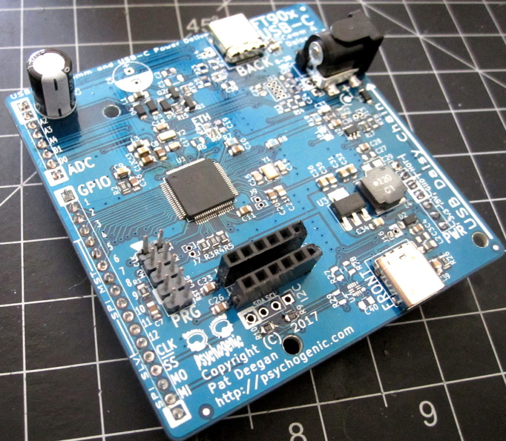
Two USB-C ports, one for the device in front and another to host a device at the back, along with power management, an SPI slave connection and a bunch of GPIO. Once a few prototypes were built, it was time to actually stick the firmware onto the chip. And this is where I found the mikroprog was a less than ideal choice.
Thing is, I was kinda miffed at FTDI after dealing with the Vinculum, because the toolchain was a mess and a horrible experience and they’re support was basically “maybe you should use the FT900s“. Hum. But since the FT90x actually uses GCC, and you can code for it with eclipse, I was convinced that the sailing would be smoother as I could rely on software I already know and trust.
And I was right: the API is relatively well documented, I still had to boot into windows to compile (boo) but most of my dev can happen under Linux with Eclipse. The FTDI/Bridgetek toolchain actually provides source code so when you’re really wondering how something works you can just poke around Bridgetek/FT9xx/2.3.2/Source/src and see what’s happening in there, which is really helpful when an example is incomplete or unclear.
Awesome: porting code from the Vinculum to this new architecture (basically had to move to a single threaded model, in order to keep a tight hand on the priorities and scheduling) was relatively pain free and I was ready to go.
Enter the mikroprog.
Mikroprog and Macroprob
Though FTDI says they’ve “working closely with 3rd party partners” like mikroE, the toolchain is completely unaware of the existence of the mikroprog device. It expects to talk “one-wire” over a UMFTPD2A device. Agh.
Ok, no problem, you think: I just payed 3 times as much for my beautiful mikroprog for FT90x and it has a “mikroProg Suite for FT90x” available for download, I will use that. click -> save as.
Well, the “suite” is a single (windows only) program with no help other than cryptic tooltips that looks like it’s visual basic under the hood.
It’s a bit flaky, sometimes no communicating with the device and spewing even more cryptic error messages. But eventually you figure out that to use it you:
- click detect–ok it sees my chip;
- skip over erase/write and go to load to select the file to burn, using “Load”;
- choose a BIN (a straight binary) or a HEX (an intel hex, which must be called .hex not ihx or anything else);
- go back up to write, click that;
If all went well, the deed is done. But neither my bin nor my hex was actually doing anything it was supposed to. Uh oh.
Maybe it was my board?
The mikroprog make it’s really hard to check this because, oh yeah, it uses a different connector (100mil/2.54mm standard pin header) than all the official FTDI/Bridgetek stuff (the FTDI programmer and Bridgetek MM900EV dev boards all use 50 mil/1.27 pitch “Micro-MaTch”). That’s ok, since they want to interop with their “click” stuff, but c’mon mikroE: add 20 cents to your BOM and include an adapter cable!
So now I was stuck: firmware and a board to test, and nothing happening from programming.
Searching online revealed nothing but a single post to the mikroe forums, someone with the exact same issue. After a week (and a bump), they finally responded. “I have never used Eclipse with the FT90x MCUs, so I am unable to help you with this, maybe some of our users could help you.” and that was it. Wow, so helpful.
The actual problem
The first thing I needed to do was eliminate hardware issues. So I downloaded the eval version of the “mikroC PRO for FT90x“.
For reasons unknown, this is mikroE re-inventing the wheel of creating a toolchain for the FT90x and selling it to you for $300. I pretty much never force my clients into vendor lock-in, so buying this (and filling my code with proprietary API calls) was out of the question, but for a quick test it did pretty well.
So I compiled a “blinking led” example, used the mikroprog to burn the result and: success.
Thus, both the programmer and board were working… I just couldn’t seem to get my eclipse-created, gcc-compiled code to do the same.
This is where, though I was having problems, the fact that source was available and the toolchain is built on standard tools saved my butt.
I started poking around the generated ELF file, and disassemble it to get an idea what was going on.
It starts out with
00000000 <_start>:
    0: ff ff 30 00 0030ffff jmp 3fffc <EXITEXIT+0x20000>
    4: 25 00 30 00 00300025 jmp 94 <watchdog_init>
    8: 43 00 30 00 00300043 jmp 10c <interrupt_0>
    c: 46 00 30 00 00300046 jmp 118 <interrupt_1>

etc etc
So the first instruction, there, is some long jump away into what is the bootloader. Then, presumably, it returns and executes codestart, which just jumps to an init (at 0x98), which does some stuff and finally calls your main().
Here’s a snippet with the codestart and the beginning of the init:
    0000008c <codestart>:
    8c: 26 00 30 00 00300026 jmp 98 <init>

    00000090 <_exithook>:
    90: 00 00 00 a0 a0000000 return

    00000094 <watchdog_init>:
    94: 01 00 00 64 64000001 ldk.l $r0,1 <_start+0x1>

    00000098 <init>:
    98: 00 00 f1 65 65f10000 ldk.l $r31,10000 <__RAMSIZE>
    9c: 80 00 40 64 64400080 ldk.l $r4,80 <.LASFDE0+0x14>
The issue is this: when you burn this bit of firmware, you know that when the device resets it’ll start off by jumping far far away into supposed bootloader… but that bootloader? It’s just not there.
It isn’t actually included into your bin/hex file. My little GPIO-blinking code, even with all the debug enabled, had a .text section that ended around 0x41f0 so the device was getting all the firmware but then it was jumping into the void and never actually returning to our init/main/actual code!
The solution
This stuff, the assembly I’ve been talking about, is added in during compilation by linking in the crt0 (c runtime initialization stuff) from
Bridgetek/FT9xxToolchain/Toolchain/tools/lib/gcc/ft32-elf/7.0.0/crti-hw.o
So there are a couple of ways I’ve found around this.
Solution #1: screw that bootloader
I’m not certain what the bootloader actually does, though I think it sets up debugging through the gdb bridge and other stuff. Still, at least for simple programs, you can just bypass the whole thing and jump straight to your initialization.
- Setup eclipse to output intel hex (or convert the .bin to intel hex using a script like bin2hex)
- Get a hold of the hex file (make sure it’s called whatever.hex rather than whatever.ihx);
- It’s text, so open it in an editor of choice.
Intel hex is just a way to encode binary as ascii, with extra fields for addresses and checksums and such. The first line of data will be something like:
:10000000FFFF300025003000430030004600300084
That first part of data, after the record type, length etc, is: FFFF3000 which is the ihex version of our first instruction:
0: ff ff 30 00 0030ffff jmp 3fffc <EXITEXIT+0x20000>
the jump to the bootloader. Well, there was another line in the disassembly above, a jump to our init:
8c: 26 00 30 00 00300026 jmp 98 <init>
The difference: the 26 versus the FFFF… so if you replace that first FFFF with 2600 in the ihex file, you’re hacking the binary so that instruction 0 is jump to init instead:
:10000000260030002500300043003000460030005C
Now, saving the changes, you can now use the mikroprog to burn a hex that will actually run your code. Yay!
Notes:
- the intel hex has a checksum field, the last two characters in the line, which must be calculated (done here already, as 5C, but adjust as needed if you modify the instruction); and
- this assumes you have the same location for your init as I do–should be, if we’re using the same version of the toolchain, but you can always disassemble the ELF yourself to find out.
Burning this hex file works, at least with the test programs I used on the FT906.
Solution #2: include the bootloader
There are surely cleaner ways to do this, but I’ve got other things on my plate and have found this to work nicely.
Burried in the toolchain, you find the onewire.py script which does the merging of the bootloader with your binary. Turns out it doesn’t use the bootloader.bin you find as you might expect, but instead a “forthboot.bin” found with the python script.
So, inspired by the code (thankyou thankyou Bridgetek for using Python and not some opaque exe file!), I created a mergebootloader.py script that transforms the output bin from eclipse to something with the bootloader included that you can use with the mikroprog to get your stuff running.
From (the cygwin) command line, you can do
 python /path/to/mergebootloader.py -h


Usage: mergebootloader.py [-x] [-b <path to bootloader .bin>]
           [-o <prefix name for merged>] BINFILE

Options:
  -h, --help            show this help message and exit
  -o OUTNAME, --out=OUTNAME
                        Prefix for name of the bin/hex file to be generated
                        [e.g. will create OUTNAME.bin]
  -b BOOTLOADERPATH, --bootloader=BOOTLOADERPATH
                        Path to the bootloader to add, by default
                        forthboot.bin
  -x                    Produce an intel HEX file, in addition to the merged
                        bin
Short version: change to the directory with your output bin (…/whatever/FT900_Debug/) and run the script with python (you do have cygwin and python installed, right? otherwise windows is hell on wheels), specifying at a minimum the name of your bin file
python mergebootloader.py MyProject.bin
This will produce a “merged.bin” that you can burn. You can also get fancy, and specify the bootloader or the output prefix:
python mergebootloader.py -o MyProjectWithBoot MyProject.bin
And then you’ll get a MyProjectWithBoot.bin instead. If you want this utility, download the script here and bask in the glow of working chips!
Conclusion
Though it’s a bit of a pain–and was a major waste of time to figure out–you can get the mikroprog working with the standard FT90x toolchain. That’s good.
My suggestion to mikroE would be that if there’s a standard toolchain, and you’re supposedly “working closely” with the manufacturer, rather than trying to lock-in your customers:
- get your programmer supported by the standard ecosystem, or make it work on your own;
- use the established connectors or at least include an adapter; and, most importantly,
- don’t strand your users, bumping expected support requests to “some of our users”
I’ll remember the time I spent on this next time I’m making a purchasing decision, and will likely avoid mikroE in the future as the “full featured” programmer (which won’t allow me to debug my code using the official toolchain) gathers dust.