If you want a simple way to use a chain of MegaBrites, ShiftBrites or anything based on the A6281 PWM LED driver , the TinyBrite library will handle all the details for you. Best of all it doesn’t need SPI, so you can drive the RGB LEDs even with ATTiny-based Arduino-compatible hardware like the Digistump Digispark!
Using TinyBrite to control these RGB LEDs can be as simple as:
chain_of_lights.sendColor(R, G, B); // yay!
The library was developed for small Arduino-compatible boards, but in addition to working with all Arduinos it should be usable on pretty much any Atmel AVR chip and probably relatively easily with other microcontrollers, too.
‘Brites: MegaBrite, ShiftBrite, and others
The Macetech LED modules take all the hardware-related work out of dealing with powerful RGB lighting.
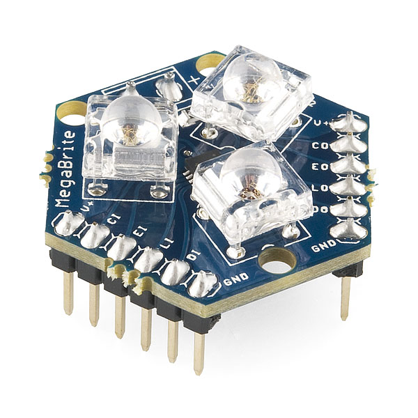
The MegaBrite, from Macetech
MegaBrites, which I’ve mentioned in the blog, are a combination of 3 sets of LEDs. Each set is equivalent to 15 standard LEDs of red, green or blue. Also on-board is an A6281 (the Allegro 3-Channel Constant Current LED Driver with Programmable PWM Control).
From the outside, the MegaBrite looks like a single, programmable, RGB LED. You can specify the intensity for each of red, green and blue with 10-bit resolution (i.e. a value between 0 and 1023).
Best of all, the MegaBrites are designed to be easily daisy-chained. This means that, using three or four pins on your microcontroller, you can control (almost) any number of MegaBrites with no additional components (other than wiring between the modules).
I’ve yet to play with ShiftBrites, but the API seems much the same with the main difference being that the megas have more juice.
How TinyBrite works
The TinyBrite library uses software to handle the serial communication with the ‘brites. The downside is that while data is being transmitted your microcontroller will be busy (i.e. you have to account for the transmit time if you’re dealing with stringent timing constraints). The main advantage of bit banging the comm in this way is that there are no special requirements for your microcontroller–there is no need for SPI support, or if it’s available you can dedicate it to something else, and you can use any three of the available pins for clock, latch and data transmission.
The simplest, “hello world!” type, example of using TinyBrite involves only 3 steps:
- creating the TinyBrite object
- configuring the pins
- using sendColor to… well, I’m sure you can guess ;-)
In code, for an Arduino, this would look like:
// include the library
#include <TinyBrite.h>

// define a few values
#define num_chained_brites    3

#define clockpin  0
#define latchpin  2
#define datapin   3

// create the megabrite chain, as a global here
TinyBrite brite_chain(num_chained_brites, TINYBRITE_AUTOUPDATE_ENABLE);
// three daisy-chained *brites, auto-updated.

void setup() {
    // setup the pins to use
    brite_chain.setup(datapin, clockpin, latchpin);
}

void loop () {
    // send colors as desired, using sendColor(R,G,B)
    brite_chain.sendColor(0, 0, TINYBRITE_COLOR_MAXVALUE); // blue

    brite_chain.sendColor(TINYBRITE_COLOR_MAXVALUE, 0, 0); // red

    brite_chain.sendColor(500, 500, 0); // any mix of RGB

    // our 3-chained brites will now look like:
    // Arduino -> Yellow -> Red -> Blue

    delay(1000);
}
More complete examples are provided with the library.
The thing to remember with a chain of ‘brites is that each color setting you specify gets “pushed” down the chain, so to set the color on 3 MegaBrites, you would send 3 color packets using TinyBrite. This way if you send “blue”, then “green” and finally “red”, the “blue” setting would start of the module tied to the arduino, then be pushed to the second, and finally be pushed down to the third leaving you with:
Arduino -> red -> green -> blue
In a case where you only have 3 modules but send more than three colors, only the last three will apply. As color settings fall off the end of the chain, they disperse into space as cosmic rays, or so say the rumours I’ve heard.
If, for instance, you want to change only the color of the middle (green) module, you need to send 3 colors anyway, to ensure every ‘brite is set to the right one, e.g. “blue”, “yellow”, “red” such that you would now have:
Arduino -> red -> yellow -> blue
Circuitry
In the simplest case, you only need to tie three pins directly from the microcontroller to the first ‘brite in the chain. From there, I just use 0.1″ 6 conductor cables to daisy chain additional MegaBrites (like these).
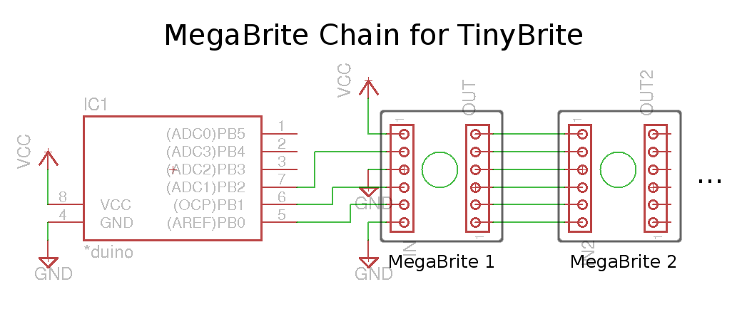
Schematic for simple chain of MegaBrites
Power
The power supply for the MegaBrites should be between 5.5 and 9V, and provide enough current to supply up to 300mA per module.
If you’re arduino has–like the digispark–a voltage regulator on-board, then you can just hook everything up to a 9V supply and be done with it. Many Arduinos, however, expect a nice 5V supply. If that’s the case, you’ll need to protect the Arduino from the higher voltage by using a voltage regulator.
Since you probably won’t be running these current-hungry LEDs from a battery, pretty much any voltage regulator will do so putting something like the classic LM7805 (e.g. this one from sparkfun) or the lower-dropout LM2937 (such as this one from solarbotics) before the arduino’s supply input should do nicely. Just make sure you have enough voltage to account for the drop out required by the regulator (e.g. you don’t want to use a 7V supply with the LM7805, though 9 volts will work nicely).
One final power consideration is how the current is provided to the modules in the chain. You can daisy chain all the MegaBrites using simple 6-conductor hookups and this will provide power as well as signal transmission. But if you have a very long chain of modules, you may want to tie the ‘brites to the source directly so that each gets its electrons straight from the power supply.6
Pull-ups
If you’ve got long lines between the chip and the first ‘brite, or just to be safe, word on the street is that you should consider adding a few pull-up resistors on the clock and data lines. This just means putting a small resistor between the line and the positive voltage, though I’ve yet to need to do this.
To find out more about pull-ups and how to figure out what value to use, see this little tutorial at sparkfun.
Enable control
The example circuit above simply ties the ~enable pin to ground, thereby leaving the MegaBrites in an always-on state. If you want finer control, the modules have an input available to control the state. To use this functionality:
- dedicate one more pin from your microcontroller to the ‘brites, tying it to the ~enable input on the first module
- specify the pin to use for enable during the call to setup:
#define clockpin  0
#define enablepin 1
#define latchpin  2
#define datapin   3

// create the megabrite chain, as a global here
TinyBrite my_brite_chain(num_chained_brites, TINYBRITE_AUTOUPDATE_ENABLE);
// three daisy-chained *brites, auto-updated.

void setup() {
    // setup the pins to use
    my_brite_chain.setup(datapin, clockpin, latchpin, enablepin);
}
From that point on, you can control the state by using the setEnabled() method, e.g.
my_brite_chain.setEnabled(true); // enable all the 'brites
TinyBrite API
Once you’ve downloaded and installed the library, it’s time to get coding. See the TinyBrite Usage and complete API pages, for details.
Related Pages: [subpages]