Here’s how to build your own TinyG “EZ-Connect”, for LitePlacer or other pick and place/G-code-controlled machines. The system’s advantages over a straight-up connection to the TinyG are mainly that it:
- decouples the TinyG from the machine (remove, replace or share the TinyG with other installations with only two cables to muck with);
- hosts a few support components (like vacuum pump and valve FETs);
- provides a few configuration jumpers (namely how the Z limits are handled); and
- has some extra smoothing caps, so even a “far away” TinyG works flawlessly
Now that its been proven to work over the last few months of operation, I’m releasing everything you need to setup your own, under a Creative Commons license (CC BY-NC 4.0). NOTE: there’s NO WARRANTY on any of this stuff–it’s all at your own risk so test and play safe.
I’ll go over all the details below but first you can get a good overview of the system, in this short video:
System Description
The system is composed of three parts: two “wings” that hook into the TinyG screw terminals (I’ve got the v8):
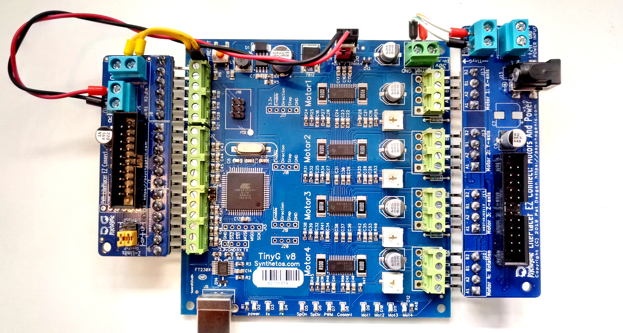
And an interface board where the wiring to the pick and place proper happens.
The motor and power wing isn’t all that interesting, but does give the option of using a DC barrel jack from the 24V power supply which I find very convenient
Main thing to note is that the supply plugs in here, so you have to use the screw terminal in the upper right to source power into the TinyG. Use decent gauge cable here.
The sense and control wing is mainly used for limit switches but has a few other functions too.
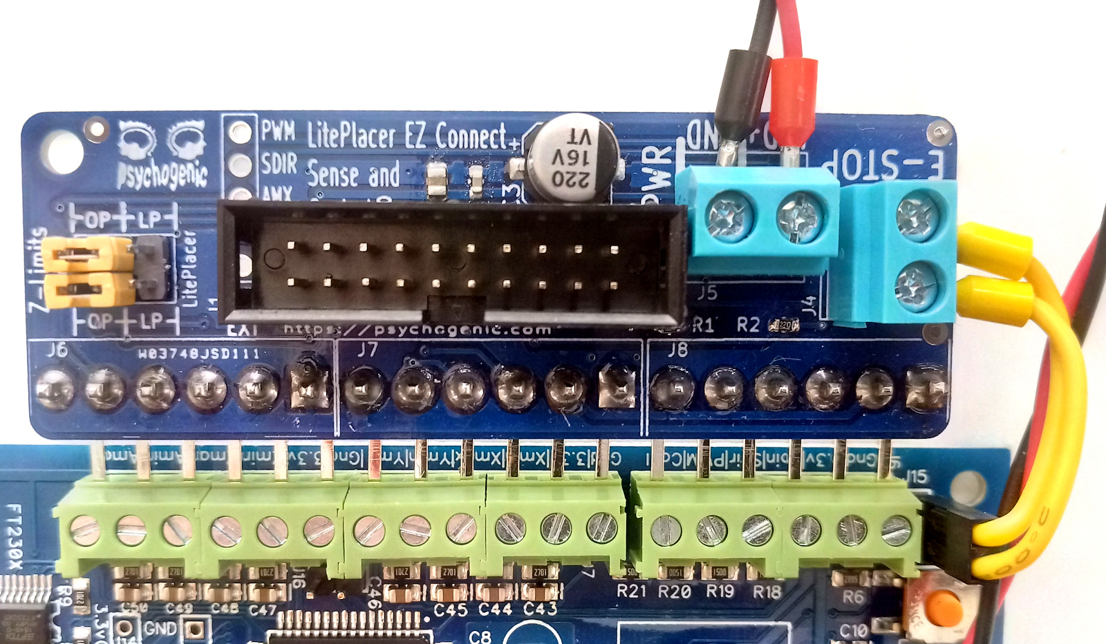
It also routes the (non-pin header accessible) LED and e-stop, and has a set of jumpers to select between OpenPnP and Liteplacer routing of the Z limit switches (shown above in yellow, on the left).
The programs interpret the Z differently, and thus the switch wiring must be inverted—these jumpers make that a snap.
Not all the terminals need be used, depending on your setup. Here’s mine as it currently stands:
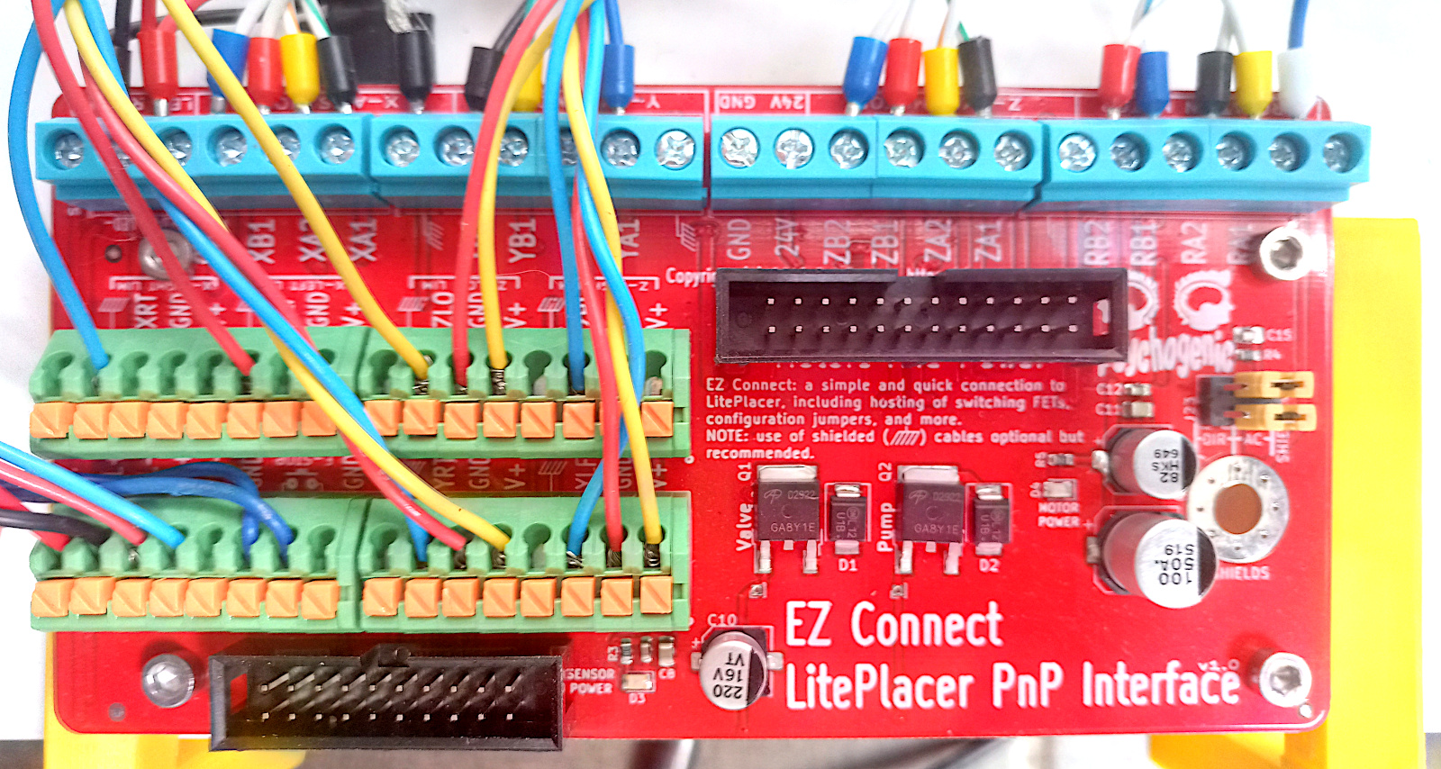
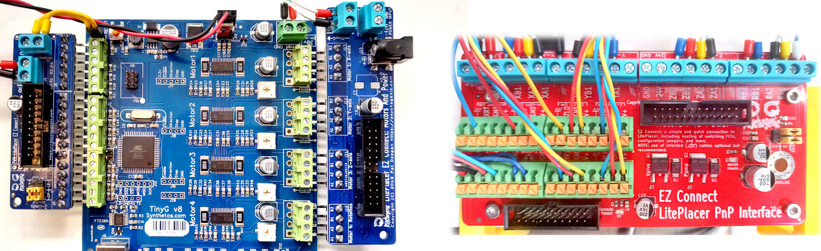
The PnP interface board takes in a ribbon cable from each of the wings and provides a set of terminals to wire up to the machine, while hosting stuff like MOSFETs for the vacuum valve and pump.
The TinyG and wings are under the table, held by those two yellow 3D printed brackets. To make things a bit clearer, here’s the same board but without all the headers and wires.
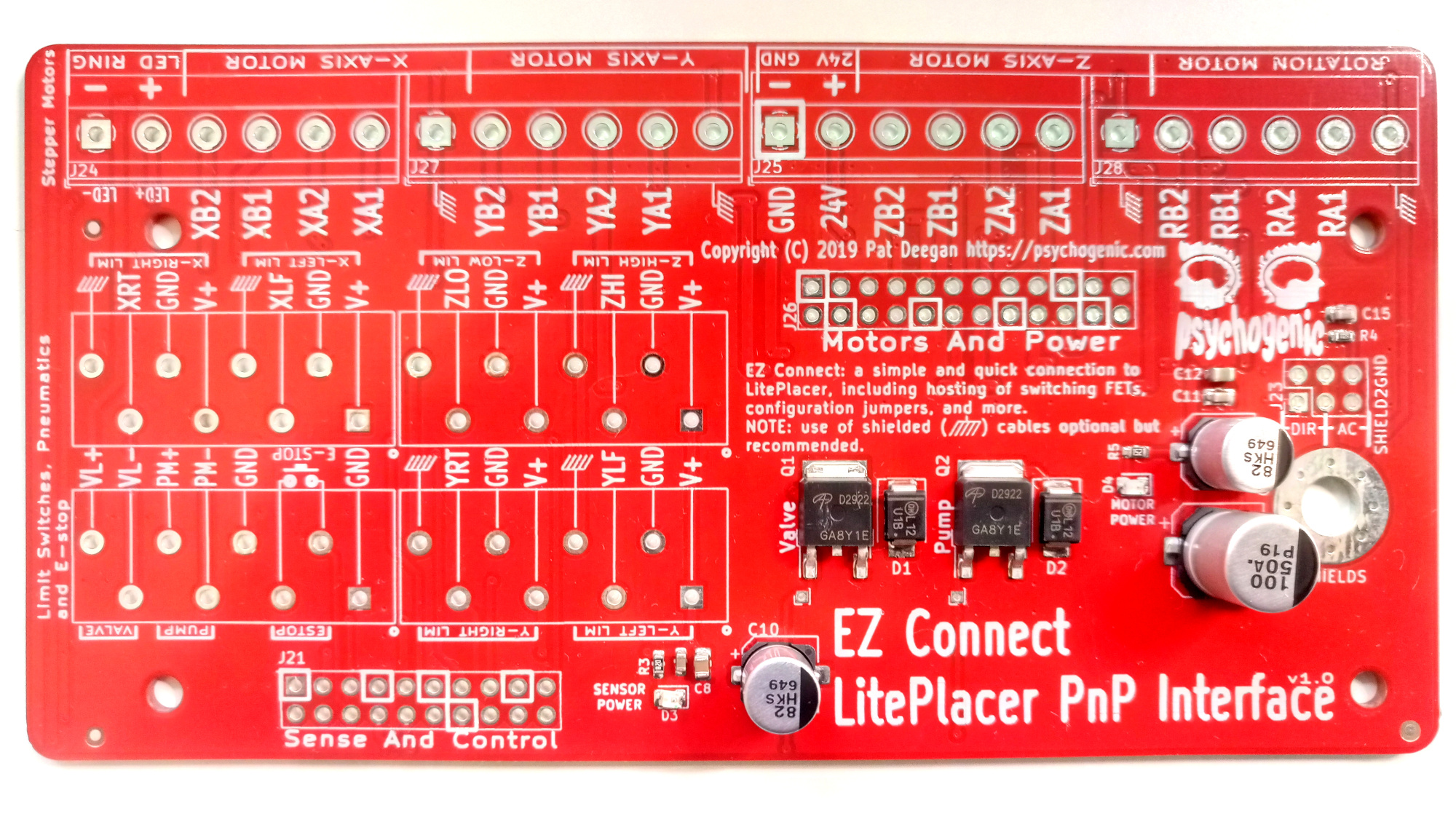
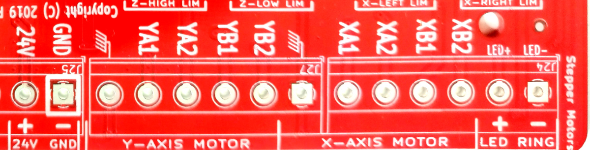
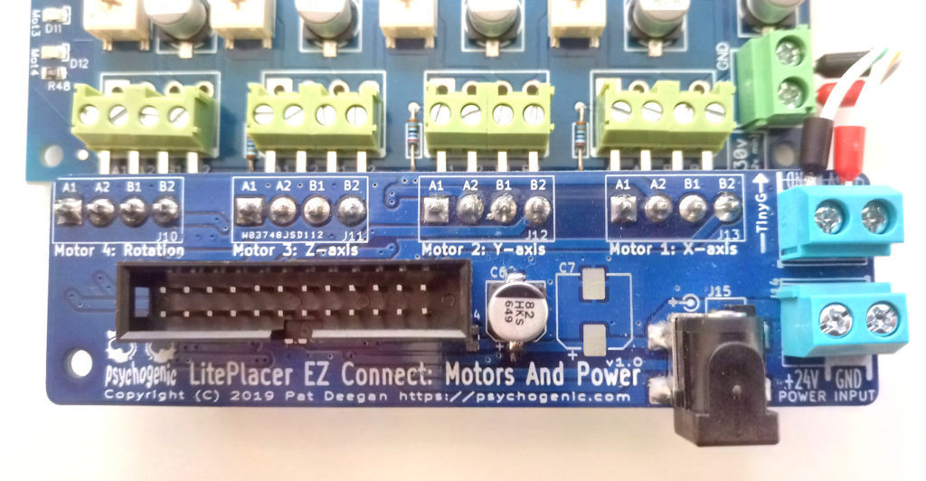
The screw terminals go to the stepper motors, and the labeling makes it pretty obvious what’s what. Those symbols next to each *A1 position is the cable shielding (if you so have), and how that’s handled is set by a jumper that either ties everything straight to ground, or only passes transients (which is what I’ve been using). There’s also a the LED ring connection, as well as a +24V/GND pair in the center, for convenience.
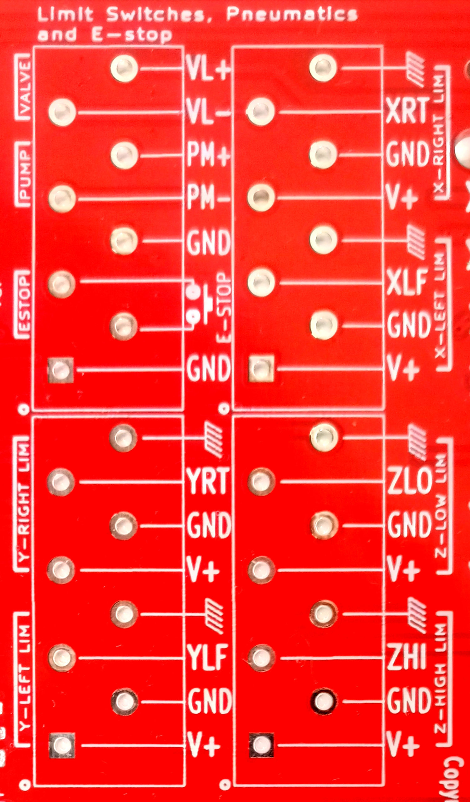
The other connections, to the limit switches and such, are made just by holding the button down and inserting the wire, in those green terminals in the populated board image, above.
The labels are abbreviated (YLF for “Y left” etc) but pretty clear. There are optional wire shield connections here too. At the top left, you can also see the valve, pump and e-stop.
The entire system can be seen in a single schematic (included as a PDF in the download below):

Some Assembly Required
The main points, when assembling, are:
- get the boards;
- get the components (valid values found assembly/EZConnectBoardsBOM.csv, with “DNP” components just being optional);
- be sure to make note of where the ribbon cable header 1-pins are (J2, J16, J21 and J26) in the placement PDF, if you’re using shrouded headers (or just pay close attention to orientation in the pics above);
- populate according to the fabrication outlines (see assembly/PnPInterface-Placement.pdf);
- install the 2×3 pin headers and their jumpers, on both the SenseAndCtrl and PnP interface boards;
- hookup the three dangly cable connections between wings and TinyG, as shown above and in schem; and
- double check the (J11/J12 on the TinyG) LED power settings and connection
Though I set things up so the ribbon cables would hopefully generate the least amount of EMI, the ones I’ve been using are just long enough to get to the TinyG under the table. I’d suggest you keep them as short as possible and use the fattest ones you can, for the 24P motor/power at least (I’ve been using 26 AWG without apparent issue).
Get Testitculitis
Once you have everything assembled, test that shit! Test it well before hooking up to anything real.
Best way to do it, I find, is to first install the wings, hook up the ribbon cables to the PnP interface board (no power) and then, one by one :
- test for continuity between a TinyG screw terminal all the way to the expected output terminal on the PnP interface PCB; and
- test for no short between that pin and stuff around it and, most importantly GND and power pins
Don’t forget the obvious continuity/short tests for the power rails (both +24V and GND, and anything that says V+ or such).
When that’s all good, double check you have VIN/GND on your supply as you (and the Motor/Power wing) expect, and that it’s at the voltage you desire. Then power up the system. Did anything blow up?
If so, well that sure sux.
Otherwise, check levels are what you expect in all the places on the interface, namely the +24V on the center of the PnP interface of the screw terminal and the voltage at the various V+ points, the FETs, etc. Hopefully, you can now safely wire up the actual machine to the PnP interface board.
Give Away v1.0 Package
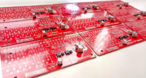
As long as I have some left, I’m giving away sets of the three PCBs (see the video) of version 1.0. It ain’t perfect, most importantly R1 gets in the way of shrouded headers on the SenseAndControl wing, and the interface board needs a patch cable to jumper ZHI.
If you got one of these, check the giveaway/v1p0FixNeeded.png image to see the v1.2 fix and where you need to stick this wire.
If you want one of the kits, watch the vid for conditions (short version: while supplies last, you handle shipping, and no jerks) and get in touch through the contact form here.
Downloadable Resources
You can get all the resources required to make and setup your own “EZ Connect” boards, with gerbers, placement, BOM, schematic and more in a single zip file here. Just remember no warranty and CC BY-NC.
OSH park or pretty much any fab should be able to handle the boards. The BOM has suggested components with digikey part numbers (’cause digi-key supports kicad, and that’s awesome).
Hope this helps you and if you have any woes, hit me up and I may be able to help.