As part of my LitePlacer pick and place machine build, the wiring was more familiar than the mechanical assembly but still pretty complex. To simplify things, and to decouple the TinyG from the machine, I created a set of PCBs to handle the wiring and host stuff like MOSFET switches and jumpers to select between OpenPnP and LitePlacer software easily.
The video gives an overview and shows it in action, and I’ll describe the system further here.
The circuit is very simple, with a one page schematic describing everything.
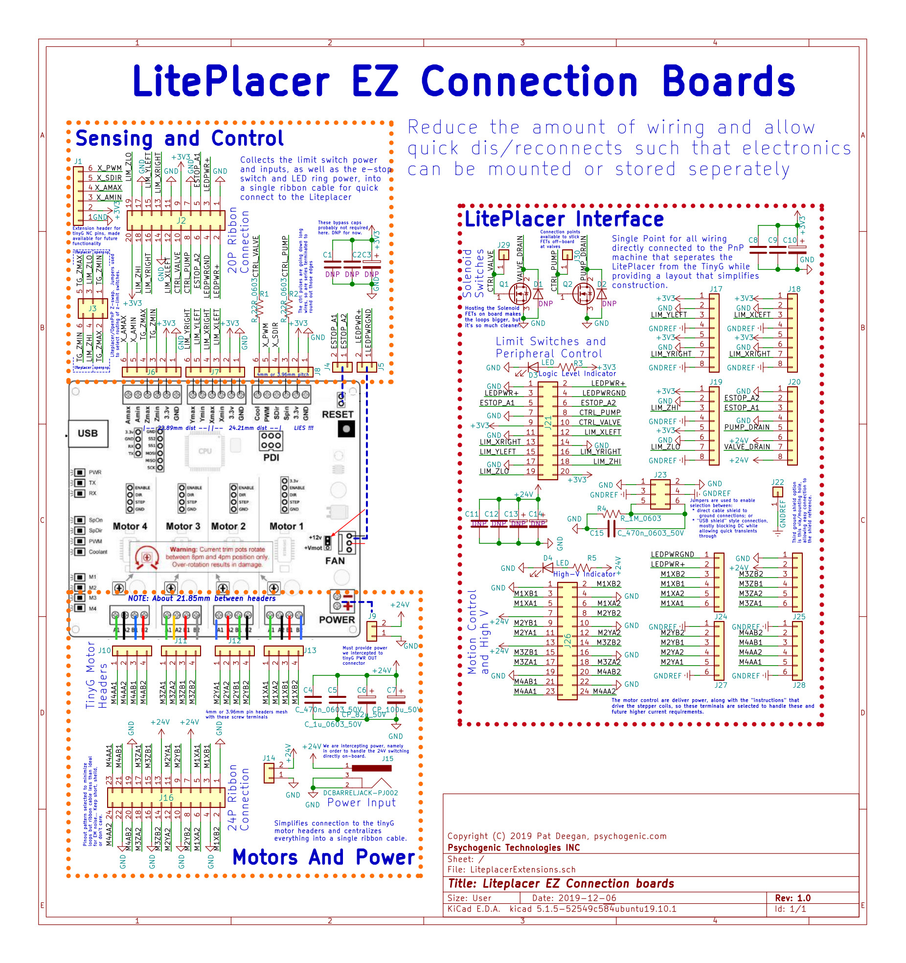
I’m using ribbon cables to have an easy system to attach and detach the TinyG. In order to help with signal integrity/noise reduction, there are copious return path wires throughout the headers, positioned strategically to minimize the loop area.
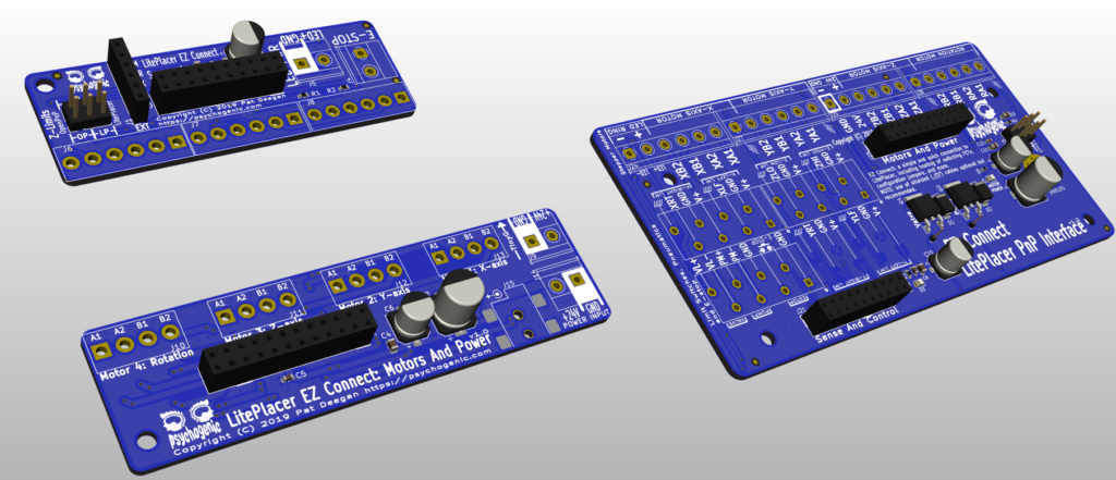
The three boards basically re-organize the TinyG headers a bit, and provide a few extra bypass caps along with the vacuum pump and valve switches and their flyback diodes, plus a couple of jumpers to configure the system for OpenPnP/LitePlacer (they use the Z limit switches in opposite ways) and to either ground the wire shields directly or just allow transients and block DC.
The fact is that you still have to deal with a bunch of wires and there’s no getting around that it’s a bit messy…
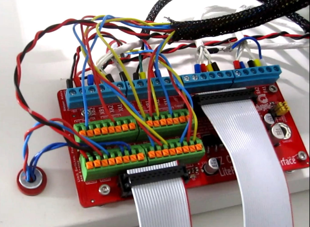
Still, that PCB is completely dumb, and I don’t mind leaving it affixed to the surface permanently as it’s unlikely to fail or need maintenance of any kind.
So, as you may have seen in that video above, the system is live and the next step is to actually do some PCBA! Yay.