You’re creating a stand-alone module to bundle a few hardware sensors, or have an independent microcontroller that stays awake and needs to wake the main system depending on configurable environmental triggers. What’s the easiest way to let this unit receive orders and communicate results? An I²C slave!

Inter-Integrated Circuit–I²C–is specifically designed to provide an easy way to do this and more. I2C isn’t a very fast protocol, and there’s a limit to how physically long the bus can be. Still, it’s simple to use and you can interact with a whole bunch of devices using only 2 wires/traces: a data and a clock line.
You’ve surely used chips and sensors that were controlled by I2C, there are a ton. In those cases, your Arduino or whichever controller, was acting as the bus master: deciding when and who to communicate with.
Sometimes you have an independent subsystem which provides services to your main MCU, or you want to package up a few sensors as a single module. Whether it’s a stand-alone PCB or part of a larger design, it can be useful to become the peripheral and act as a slave device.
Doing so is easy, but as a slave device there are a few gotchas that are worth taking note of.
Here I’ll go a bit further than the basic tutorials that just tell you to join as a slave and use two callbacks, to point out a few traps and show some more advanced handling.
We’ll use the Arduino SDK‘s standard TwoWire interface because lots of people know it, it’s available for pretty much every microcontroller around and because it makes the differences between chips disappear.
Basics
Getting started is straightforward. You need only:
- join the bus as a slave
- create and assign a function to receive data from the master
- create and assign a function to provide data to the master
Joining the bus
Rather than the usual Wire.begin() call, you can pass an address to begin to let the Wire library know you’ll be on the bus as a slave device:
Wire.begin(ADDRESS);
Which I2C address to choose?

The addressing system is both one of the strengths and weaknesses of I2C.
It’s great because it allows a hundred devices to talk to each other on a bus with only two wires.
It’s annoying because the address space is limited and it’s hard to avoid collisions. It’s terrible because it’s meta information. You can’t see addresses from the schematic and can’t tell who the bus master is. You can’t know which physical devices are interacting on a live bus, even with a logic probe tied to everything, which makes it hard to track down a disruptive or faulty device.
Old style/standard I2C addresses are a single byte but, to support the bi-directional data line, you only get 7 bits worth for device addresses. Thus, your address must be a value smaller than 128 (0x80). Additionally, there are a few addresses reserved by the protocol leaving you only 112 values to choose from.
In short, you should choose an address that:
- is greater than 7;
- is smaller than 120 (0x78); and
- isn’t used by any other component on your bus.
So, anything between 8 and 119 (0x77), inclusive, that isn’t already taken.
That last point is easy if you’re building a peripheral into a static circuit board but if this peripheral is modular and designed for general use, you can’t know which other components will be present.
It’s a good idea to try and choose an address that isn’t too popular, but really the best course is to allow for user address selection (more on that below).
Receiving data from the master
Once you’re on the I2C bus as a slave, you can get down to business. First allow your slave to receive orders. The simple explanation is that you need:
- a function with a void(*)(int) signature to receive the commands; and
- to let the Wire know about that callback function
So, any function that looks like
void handleDataComingInFromMaster(int num_bytes) {
  // we've received num_bytes bytes
  // from the boss
  // now, do something!
}
will do the trick. Then, likely in the setup function, we tell Wire about it.
Wire.onReceive(handleDataComingInFromMaster);
Done! Well, we still aren’t actually doing anything. To get those bytes, you need to read them in, first. The callback is passed the number of bytes received, so that’s pretty easy:
// MAX_BYTES_ILL_EVER_GET -- some reasonable
// value, according to your protocol
#define MAX_BYTES_ILL_EVER_GET  20

// the callback
void handleDataComingInFromMaster(int num_bytes) {
 // we've received num_bytes bytes from the boss

 // somewhere to stash them
 uint8_t in_buffer[MAX_BYTES_ILL_EVER_GET];

 for (int i=0; i<num_bytes; i++) {
  if (i < MAX_BYTES_ILL_EVER_GET) {
     in_buffer[i] = Wire.read();
  } else {
     // uhm... too much data, just drop it
     Wire.read();
  }
 }

 // now do something with those num_bytes bytes, stored in
 //  in_buffer[] ...

}
Responding to data requests
The other side of the equation is when the master wants to get some data from our side. It will call something like:
Wire.requestFrom(YOUR_SLAVE_ADDRESS,
                          SOME_NUMBER_OF_BYTES);
and we are expected to provide those bytes back to it. To handle this, our slave:
- implements a function with a void (*)(void) signature; and
- tells the Wire to use that function as the callback
That’s just a function like:
void handleDataRequestFromMaster() {
  // provide the data…
}
and a call to assign the callback, normally in your setup()
Wire.onRequest(handleDataRequestFromMaster);
Interestingly, that master is waiting for SOME_NUMBER_OF_BYTES but you aren’t actually told what that number is, so it’ll be important to somehow agree beforehand on what will be transmitted during a given request. Doing that transmission is easy: just use one of the available write() methods, e.g.
void handleDataRequestFromMaster() {
  // provide the data, here something boring and static
  uint8_t return_buf[] = {'h', 'e', 'l', 'l', 'o'};

  // hand it over to Wire, so it can stick it in its out buffer
  Wire.write(return_buf, 5);
}
And that’s it for the basics. We’ve got a slave device that joins the bus, accepts incoming data and responds to data requests and that’s where many tutorials end. The problem is that it’s both boring and glosses over some of the trickier points of creating a well behaved peripheral.
So now we dive a little deeper.
Going further: a more realistic I2C slave device.
Protocol
Before anything else, you need to establish the kinds of messages that will be exchanged between the master and the slave. This API is the protocol that both sides agree to use during interaction.
In real life, you’ll have messages of different lengths. It’s a good idea for the slave to allow for feedback after any command was issued but to leave it up to the master whether such feedback will actually be requested or not.
So, step 1, a table of commands and (potential) responses. We’ll say that each message is at least one byte long (duh), and that that very first byte will always be a command (or register) ID. A simple example
| Command | Interpretation | Payload | Tot Len. | Response |
| 0x00 | Get status | — | 1 byte | 1 byte |
| 0x01 | Set time | 4 bytes | 5 bytes | 1 byte |
| 0x02 | Get time | — | 1 byte | 4 bytes |
This has 3 messages from the master that we agree to handle, one of which includes an extra 4 bytes of payload data. Each command received may be followed by a requestFrom() on the master side, for a certain number of bytes, depending on the last command it sent.
Our job will be to:
- Wait for incoming bytes from the master
- process all complete messages
- write appropriate bytes to the wire, when requested
Encapsulation
To keep things clean and organized, we’ll define a class that represents our peripheral, maintains state and does whatever work it needs to do.
Other than sensing or whatever your slave’s job actually is, it’s role is to implement the API we’ve defined. It will understand incoming messages and provide appropriate data to any request.
/* MyI2CPeripheral
 * A class to centralize our peripheral's state
 * and message processing.
 */
class MyI2CPeripheral {
  public:
    MyI2CPeripheral();

    /*
     * getResponse -- returns an appropriate buffer,
     * and its length, according to whatever commands
     * have been received prior, or defaults.
     *
     * SlaveResponse is just a struct with:
     *   - uint8_t * buffer;
     *   - uint8_t size;
     */
    SlaveResponse getResponse();


    /*
     * expectedReceiveLength(REGISTERID)
     * Returns the number of bytes to receive for a given
     * command or register, REGISTERID
     */
    uint8_t expectedReceiveLength(uint8_t forRegister);

    /*
     * process(BUFFER, BUFLEN)
     * Process incoming data from master.
     */
    void process(volatile uint8_t * buffer, uint8_t len);

};
With this class, we can create a global singleton:
/*
 * I2CDevice -- the global that represents
 * this device and handles messages
 * and state.
 */
MyI2CPeripheral I2CDevice;
Requests for data
We’ll start with responses, because it’s so simple. Keeping all the state and handling in an instance of this class, the onRequest() handler can just be:
/*
 *  i2cRequestEvent
 *  this will be called when the master is asking
 *  to get some data from our peripheral device.
 */
void i2cRequestEvent()
{
   // get the response (the I2CDevice knows what to say)
   SlaveResponse resp = I2CDevice.getResponse();

   // write it to the out buffer
   Wire.write(resp.buffer, resp.size);

}
The important thing to note is that you want to keep things snappy and write all your data to Wire immediately, here, inside the callback.
If you take too long, at least some implementations on the master side will read in a bunch of garbage values (0xff) and then move on, and when you finally get around to doing your write(), you’ll be filling the out buffer with out-of-date values and wind up out of sync with your master (i.e. returning data for the last command, when a new request comes in).
Receiving data
The simple approach to receiving data is to implement a callback that gets bytes and do whatever needs doing right in there. It can work fine. Or not.
Data comes in whenever the master decides, and that callback is triggered asynchronously by some underlying interrupt service routine.
It’s best to keep processing to a minimum in an ISR. Also, we’d like to allow for maximum flexibility, namely handling larger messages, even ideally being able to handle the case where a large command is split up into multiple triggers of the callback.
So a better solution is to use some buffering: collect the data for a full command/message as it comes in and, when its complete and ready, queue it for processing.
If you’re expecting large messages, and lots of them, to come in quickly you’d probably want to use some sort of ring buffer, maybe dynamic allocation, etc.
A middle ground is just to buffer messages in some holding space until the message is fully received, then move it to somewhere else for handling in the main loop. This is relatively simple, and yet allows for a second command to start coming in while the last one is still being processed.
Here’s how such a general purpose, buffered, handler might look. Let’s start by creating two bins for our data:
/* Two sets of buffers...
 *  receivedBytes[] will store incoming bytes as they are accumulated
 *
 *  pendingCommand[] will hold commands as they come in from the master
 *  and be processed in our main loop.
 */
volatile uint8_t receivedBytes[RCV_COMMAND_MAX_BYTES];
volatile uint8_t receivedByteIdx = 0;

volatile uint8_t pendingCommand[RCV_COMMAND_MAX_BYTES];
volatile uint8_t pendingCommandLength = 0;
Note that everything here is marked as volatile: the values might be modified out-of-band (by the ISR) at any time, so we don’t want the compiler doing any optimizing away. In such cases, volatile is our friend.
Now the callback:
void i2cReceiveEvent(int bytesReceived)
{
  uint8_t msgLen = 0;

  // loop over each incoming byte
  for (int i = 0; i < bytesReceived; i++)
  {
    // stick that byte in our receive buffer
    receivedBytes[receivedByteIdx] = Wire.read();


    // now, we're sure we have _at least_ one byte in the buffer
    if (! msgLen) {
      // this was the first byte of a message,
      // so we couldn't know the
      // expected message length until now...
      // ask our device what to expect:
      msgLen = I2CDevice.expectedReceiveLength(receivedBytes[0]);
    }

    receivedByteIdx++; /* increment in-byte counter */

    if (receivedByteIdx >= msgLen) {

        // we have a complete request/command in our buffer!

        // 1) copy that into our pending commands buffer
        // could use memcpy, we do it manual style:
        for (uint8_t i=0; i<msgLen; i++) {
          pendingCommand[i] = receivedBytes[i];
        }

        // 2) tell the main loop we've got something
        // of interest in pending cmd buffer
        pendingCommandLength = msgLen;

        // 3) zero our in-bytes buffer, to start
        // the next message
        receivedByteIdx = 0;

        // 4) zero our expected msgLen, so we'll refresh it
        // for the next command
        msgLen = 0;
    }
  }
}
The things to note are that:
- we accumulate incoming bytes into receivedBytes[].
- if we don’t know how many bytes to expect, we ask the device to figure that out
- when we have enough for a complete message of this type, we move it to pendingCommand[]
With this approach, as long as we don’t get more than one complete message per interrupt, we can process a message while receiving bytes for the next.
Main loop: actually processing the requests
Once the basic setup() is done
void setup() {

  // SETUP wire
  Wire.begin(MY_SLAVE_ADDRESS);
  Wire.onRequest(i2cRequestEvent);
  Wire.onReceive(i2cReceiveEvent);

  // do other setup you may need...

}
incoming data and requests will be handled and any commands received will get shoved into the appropriate buffer. The main loop() will be responsible for checking if any pending command is present, and processing that.
Something like this would work:
/*
 * main loop.
 * Here, we'll just loop around and handle
 * pending commands when they come in.
 */
void loop() {

  if (pendingCommandLength) {
    // oh my, we've received a command!

    // if you're going to be very slow in processing this,
    // you could copy the contents of pendingCommand[]
    // over to yet another buffer.
    // Here we just do it "real time" for simplicity

    // 1) process that command
    I2CDevice.process(pendingCommand, pendingCommandLength);

    // 2) zero that flag, so we don't process multiple times
    pendingCommandLength = 0;
  }

  // do anything else that needs doin'
  I2CDevice.doThings();

  // main thing is that you must process any pendingCommand
  // before the next full command bytes come in through the wire

}
We’re using the pendingCommandLength as a flag to know if anything new has come in. When it’s non-zero, we pass the pending command on to our device object’s process() method and zero the flag.
The main loop is also where we can do routine maintenance, scans, etc. The thing to remember is that you always want to keep reacting to master requests as the top priority. This can be done a number of ways, but it boils down to checking for requests and processing them in a timely fashion.
Going Further
With all the above, you’ll have an I2C peripheral that is responsive and can perform its duties well. If you want to go the extra mile, here are a few extra hints that can shift it from good to awesome.
Configurable addresses
The first thing to do is to deal with the downside of the limited I2C address space. Though less important if your device is part of a larger printed circuit board, if it is to be a modular system–some standalone module on its own PCB, designed to be hooked into arbitrary boards–then you really should allow a bit of flexibility in terms of slave address.
Some manufacturers provide chips that have a default address that can be changed through an API. You send a command to the default slave address saying “change your address to XYZ” and then the master uses XYZ when interacting with the slave.
That’s extremely flexible, but is even more meta information to keep track of. In essence, it’s a nice way to lose your device, and then you have to putz around scanning the bus to figure out what the address has been set to.
A better approach, if you can afford the pinnage, is to provide the same system as many I2C chips: use a few I/O pins.
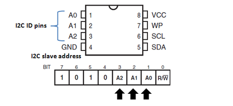
If you define the address as in the image above, and setup those Ax pins with input pull-ups, then the default address here would be 0x57. By tying any of A[0..2] to ground, the end user can select any address between [0x50, 0x57].
This allows for some leeway in dealing with address collisions. It also allows your end user to have up to 8 of your device hooked into their circuit without conflict.
Finally, I love the fact that you can tell which device is which by looking at the schematic.
Mission Critical Applications
We’ve got a module that, in theory, does its job but really we’ve just been expecting the master to throw us a command and assume all went to plan (i.e. hope for the best).
If you really want to make certain that commands have been received and processed, there’s little built-into the I2C layer to help you out.
You can, however, enhance your protocol in various ways to increase its reliability.
One simple way is to augment the replies to include, say, a sequence counter. So you just track the number of commands processed, and include this number in the status reply, or even in all replies. That way, the master can decide how much it cares and track, or not, the sequence number according to its activity.
One step up is to expand the definition of “command” to always include a pseudo-random token (decided on by the master), that will be echoed back in replies until the master changes it in the next command:
Commands are all:
COMMANDID  TOKEN  [PAYLOAD]
Or, if you have the time/processing power, you can move more effort onto the slave side and, for instance, calculate a checksum of each incoming command and report that back to the master in your status response.
In short, there are many methods from simple sequence counters to complex checksum or SYN/ACK synchronization routines you can use. Whether these are required, and the level of complexity involved, should be decided based on how important the communications really are and how likely they are to fail to get through properly.
Your own I2C device
So now you can create i2c slaves for a host of applications. These can run on pretty much any microcontroller, but more often than not are best run on smaller chips that are cheap and well suited to being dedicated to the task of servicing a master for a specific job, like the ATTiny family.
All the source code show here can be found bundled in a small Arduino I2C slave script, along with some additional stub functionality to get you going.
I wish you luck in your projects. If you hit a particularly tough spot and are tired of slaving away at it (ugh), get in touch if you need a hand.
Final note: sometimes I2C isn’t the best choice and the advantages of SPI start to shine. Have a look at this previous post to find out how to create an SPI slave device.