Designed to interact with a 16-bit I/O expander, the firmware was ready for testing. Though I was still waiting on parts, I wanted to make sure it would all work as expected. What’s an impatient developer to do? Create his own SPI slave to replace the missing part, of course!
If you’ve gotten anywhere beyond getting an Arduino to print “Hello World” to the serial port, you’ve probably already had to talk to various sensors and modules, acting as as master of SPI lines. However, sometimes you need to go the other way ’round and actually play the part of the sensor/controller/whatever chip… this is where you take on the role of the SPI Slave. Here I’ll cover the reasons and methods used to implement an SPI slave that other ch ips can control.
Context
For this project, the Atmel ATTiny841 were selected because they can run at 8MHz at low voltages, have 12 I/O lines and a hardware slave I2C interface. The fact that they’re literally tiny and happen to be dirt cheap helped make them a good choice, too.
The MCP23S17, for its part, is cool because it has those 16 pins to play with, you can setup interrupts in various ways, it has a very fast SPI interface, all while running at low voltage as well.
So the project combines the two for a neat application which I’ll be talking about in a future post.
So the PCB was designed, and firmware for an ATTiny841 AVR was just about ready but the PCBs weren’t back from the fab and I didn’t have an MCP23S17 on hand yet.
I decided it’d be useful to create an SPI slave that would simulate the behaviour of the I/O expander, allowing me to test my code and see things from the perspectives of both the microcontroller (controlling the expander) and from the slave’s point of view. That way, I’d be able too see what the slave chip is actually receiving, as well return whatever type of response I want to the driver, without having to actually mess around with any digital inputs.
The techniques described here would of course work for a real peripheral device as well, since rather than simulate the MCP27S13 you could be returning sensor data, storing bytes or whatever you want.
Hardware for Slave
The ‘841s I had on hand to use as the microcontroller were SOIC-14 (surface mount) parts: not impossible to breadboard with some finagling… However, I try to also keep some general purpose SMD breakouts around, like these:
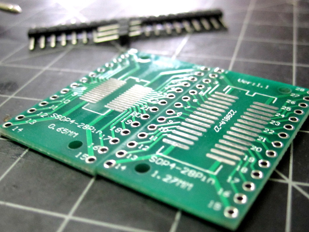
which are perfect in this case, since they have room for 28 (50mil/1.27mm pitch) pins, and the Tiny841s have 14 pins each. In a couple of minutes, I had a nice little breadboardable board hosting two ATTiny841 chips, one atop the other:
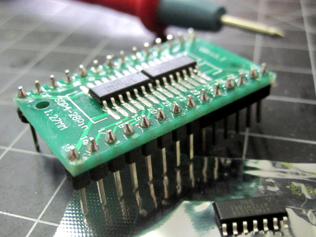
Breaboarding the two chips
The top mcu would as my microcontroller (to host the application firmware) and the lower would play the role of the MCP23S17, using it’s hardware SPI pins to do its thing as an SPI Slave device.
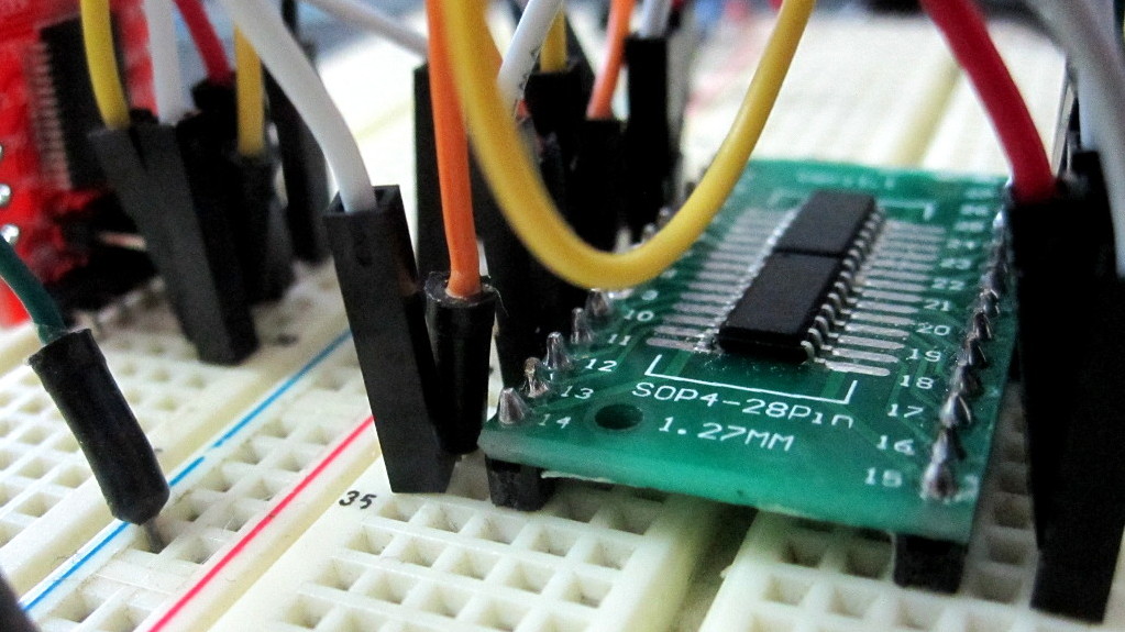
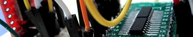
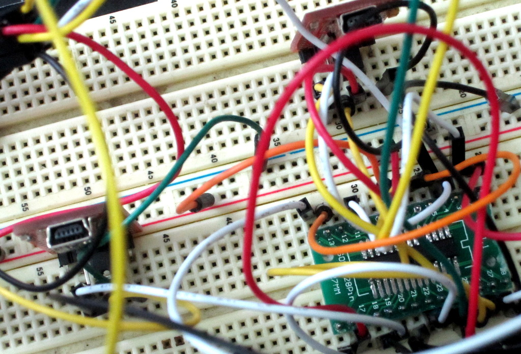
Slotted into a breadboard, I tied them to power and to each other to replicate my eventual circuit’s layout, as well as hooking up each 841’s UART to an FTDI-type USB-to-Serial module for monitoring some debug output, and finally adding connections to an ISP programmer so I could burn firmware to the chip I was working on while leaving it in place.
I dislike having such a rat’s nest of wiring, but avoiding the need of a custom PCB at this stage and having access to the Serial lines on both devices was worth some temporary spaghetti.
SPI Slave Code
To write the SPI slave code, I kept things simple and used the ATTinyCore — a great system that provides an Arduino SDK for pretty much any ATTiny, and is quite informative about what each of the controllers can support and how to use it.
Since the ATTiny441/841 have hardware SPI built-in, the standard SPI library works as you’d expect when acting as a master. For slave use, you get a little closer to bare metal, though hardly.
The Easy Stuff
In short, you need only do three things:
- Setup your SPI lines and SPI interrupts
- Enable the Master-In, Slave Out (MISO) line, when it’s your turn; and
- Transfer bytes on the line.
For this example, we’ll keep things as simple as possible and avoid using interrupt handlers an the like, so setup is little more than:
void setup() {

  // Initialize SPI pins.
  // the clock, master-in and select
  // are obviously all inputs
  pinMode(SCK, INPUT);
  pinMode(MISO, INPUT);
  pinMode(SS, INPUT);

  // our output is, initially, put
  // in high-z mode by setting it
  // as an input, too, so we allow
  // other slaves on the SPI bus
  // to work.
  pinMode(MOSI, INPUT);


  // Enable SPI as slave.
  // Here we're using bare-metal AVR
  // register stuff:
  SPCR = (1 << SPE);

}
Now, in the main loop, our job is to detect when it’s our turn to speak and, when it is, to transfer bytes on the SPI MISO line as appropriate.
To do this, we can keep track of when we’re being selected. If a read of the SS line is LOW (or false), then we are being addressed. Otherwise, we should keep quiet. The added twist is that we want to toggle the mode of our output line accordingly. So:
// a global flag to keep track of our use
// of the MISO line
bool AmUsingOutputLine = false;

void loop() {


  if (digitalRead(SS))
  {
    // SS line *not* selected

    if (AmUsingOutputLine) {
      // But we *were* using MISO, previously,
      // so put the slave-out line back
      // into high-z
      pinMode(MISO, INPUT);

      // am no longer selected, remember that:
      AmUsingOutputLine = false;
    }
    // in this case, we do nothing unless
    // being "talked" to, so we just return
    // and loop again
    return;
  }

  // when we get here,
  // the SS line is LOW, so we *are* selected


  if (! AmUsingOutputLine ) {
    // This is the first loop with
    // SS LOW, i.e. we've just been selected
    // so prepare the slave-out line for our
    // use:
    pinMode(MISO, OUTPUT);

    // remember that that's done
    AmUsingOutputLine = true;
  }

  // ok, now we handle communications...
  // TO BE CONTINUED...

}
In the above, we’ve handled moving from idle (SS high/not selected) to being addressed through SPI (SS low/selected), and we’re switching between using the MISO line to output bits are leaving it available for other SPI devices to do so, depending on state. Finally, it’s time to actually transfer some bytes.
The function can look a little cryptic, but is simple:
// SPItransfer BYTETOSEND
// returns: byte received
byte SPItransfer(byte value) {

  // start sending value to master
  SPDR = value;
  // wait until done
  while (!(SPSR & (1 << SPIF)));

  // get value received from master
  return SPDR;
}
The SPDR is a neat Atmel abstraction of the SPI shift register. What you “put in” (assign to it) gets sent out to the other end, and what you “take out” (when you read it) is what was received at the same time your byte was being sent. Because it takes time for the bits to be sent across the SPI lines, you have to wait for a magic SPI interrupt bit (SPIF) to appear in the SPI Status register (SPSR), which is what that while() loop is about.
And that’s all you really need to get going. However, there are some caveats involved in this.
The Harder Stuff
Here’s an example of the logic levels on each of the interesting lines for an ideal SPI transaction, based on a request to read the I/O lines for the MCP23S17:
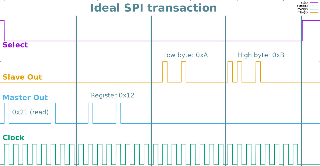
The above is SPI perfection. The master selects the device, sends an appropriate “OpCode” to read this device, sends the register address (0x12) and then keeps on clocking the SPI to fetch the two bytes representing the state of the I/O expander inputs (shown here as 0xA for port A inputs and 0xB for those on port B).
In reality, what happens on the SPI lines is less perfect. For one, the master side has to spend a few of its internal clock cycles setting up the SPI byte to send and retrieving whatever came in, so there’s some extra delay between the SCK clock cycles between each of the four bytes.
This is actually good news for you, the SPI Slave creator. The reason? Unless whatever you are replying is hard-coded or otherwise static, you’re going to need a little time to prepare and select whatever value you’ll be returning.
The really bad news is this: if you somehow manage to skip a beat, you’re gonna have a bad time. Say that, once you’ve been selected and setup the MISO line, you get the first transmitted byte and output some debug info:
  // first byte is always op code
  byte opCode = SPItransfer(0);

  // see if this is a read (first bit is set)
  bool isRead = opCode & 0x1;

  // Now, tell me all about it
  Serial.print("Have connection from master for ");
  if (isRead) {
    Serial.println("read!");
  } else {
    Serial.println("WRITE!");
  }

  // now we need the register
  byte registerAddress = SPItransfer(0x0);

  // do stuff...
Well, that looks nice. However, those print statements take time to execute and perhaps worse, they’re using interrupt routines and handlers to play with the hardware UART, so even if your code was interrupt driven, you don’t know what kind of influence they might have or disruptions they might cause unless you go under the hood and really know what’s happening.
The short of it is that code such as that will cause problems like this:
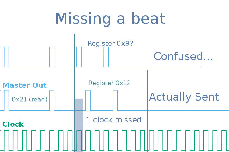
So you got that first byte, but then by missing a clock cycle the next value you recieve is right shifted. In this case it converts the register value the master wanted to send, 0x12, to 0x9 and the slave has no idea what the master actually wanted.
Even worse, even if you only miss that single clock, eventually you’ll wind up with a total number of clocks that isn’t a multiple of 8. That means that you’ll be spending time stuck in that loop:
  // wait until done
  while (!(SPSR & (1 << SPIF)));
in the SPItransfer() function.
The solution here is to keep things snappy and to know when you can safely play with interrupts or spend time doing other things. You can exchange processing time for firmware size by avoiding calls to functions altogether (since these require internal clock cycles on your slave, pushing arguments and pointers on and off the stack) by inlining the code. A simple
// SPItransfer BYTETOSEND
// returns: byte received
inline byte SPItransfer(byte value) {

  // start sending value to master
  SPDR = value;
  // wait until done
  while (!(SPSR & (1 << SPIF)));

  // get value received from master
  return SPDR;
}
should work for that function, as well as keeping critical sections within the main loop, rather than as distinct functions.
The other thing to do is to know how your slave will be used and code accordingly, namely by taking time to do work after a given transaction completes or whenever we’re not selected.
Since, in this example, every transaction starts with:
- Opcode (1 byte)
- Register Address (1 byte); and then
- 1 or 2 bytes, in or out
It was always best to get those first two bytes in one go, then act appropriately. So
  // ... we've been selected and are ready...
  // there are always 2 bytes coming in from master,
  // get those now:
  byte opCode = SPItransfer(0x0); // OPCODE with read/write bit
  byte reg = SPItransfer(0x0); // get the register address
  isWrite =  !(opCode & 0x1);
  switch (reg)
  {
     // do the right thing...
  }
Also, I knew one sequence of import would be:
- Setup the pins on port B as output and set their levels, then
- Read the values on the inputs of port A
The trick was to prepare the values to return for port A after that first step was done, rather than before the second step when they’re being requested and time is of the essence. That way, all the work is done while the master is busy preparing to make its next request.
Hopefully, this guide will have helped you get started writing your own sensor or peripheral device with an SPI interface. If you do make an interesting module, or need help in doing so, please get in touch and let me know. Have fun!