I love the Arduino platform, especially for prototyping, and have been playing with the Atmel ATmega chips for a long while. Once you’ve designed your project, some of the smaller derivatives (like the Ardweeny I’ve mentioned before) are cheap enough to leave embedded everywhere and, in any case, you can always move from an Arduino device to a DIY board, designed around the same microprocessors.
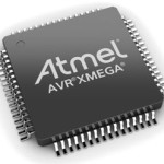 However, there are times when you’d like to leverage all the Arduino tools and libraries but need a little more oomph. That’s when I turn to the XMEGA family of MCUs.
Thanks to Xmegaduino, you can get the benefits of upgrading to a faster and better equipped microcontroller without sacrificing the ease-of-use inherent in the Arduino ecosystem.
The Xmegas are MCUs that use the same AVR enhanced RISC architecture as the ATmega’s found in Arduinos. This means that, with a little tweaking and the help of Xmegaduino, you can easily transition projects to the new platform. I’ve already developed a number of products based around the xmega+Xmegaduino combination, and have used the SerialUI, EvoLink, SPI and other many other familiar libraries seamlessly.
The main advantages I’ve found while using the XMEGAs are:
- Fast: 32MHz, with no external components
- UARTS! Lots and lots of hardware serial ports are available!
- Multiple SPI ports
- Flash space: anywhere from 32k to 384k available for your programs
- RAM: up to 16k of RAM, that’s 8 times more than on a Mega328.
- Between 26 and 50 I/O pins
- External interrupts on all I/O pins
- A ton of peripherals: in addition to the USARTs and SPI, there are hardware crypto (AES/DES), CRC (16/32)
- Low power
- An event system that lets the chip handle various events (like comparator or timer overflows) in the background using an independent bus
- Bootloader space: up to 8k available for bootloader code, if you’re into that sort of thing.
- JTAG debugging
and you can all that for under 5 bucks.
Using the xmega, I’ve had enough space to write a bootloader that verifies new firmware cryptographically, flashes the chip with the upgraded firmware and can even back-out of a failed update, restoring the original program.
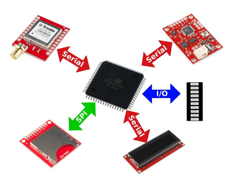
Recently, I had a project to prototype a device that interacted with a number of components:
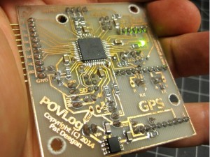
The main board needed to use 4 serial lines to communicate with a GPS, an inertial measurement unit (Razor 9DOF IMU), a two-line LCD and a remote terminal for SerialUI/Druid4Arduino configuration and control. An SPI port was used to interface with an SD card, and there were enough pins left over to provide for power switching on the external modules, input buttons and a 10 LED bargraph!
If you’ve ever hit a wall during development, either for lack of space, RAM, pins or peripherals, then start exploring the XMEGA. Here we’ll review how to choose the best microprocessor for your needs, go over the pros and cons of using these chips, setup an Xmegaduino development environment and xmega-specific coding. After that, you should have everything you need to get started using xmega in your own projects.
Choosing an XMEGA
There are a whole bunch of xmega chips available, and choosing the right one can be frustrating. There are a few development boards available (the Atmel xplain, akafuino, etc) that can get you started, but even then you need to know what you’re actually choosing when you select a specific chip.
In short, the xmega’s all have names of the form:
Xmega NN FAMILY M [U]
The NN is the easiest part: 16 means 16k of flash, 32 = 32k, etc. So ATxmega128D4 has 128k of flash space for your programs (the RAM, EEPROM and bootsector sizes go up in spurts along with this value).
The “family” is arranged like grades in primary school: i.e. “A” is a bunch more powerful than “D”. All the families will support the same architecture, but some of the fancier hardware peripherals, e.g. cryptography, won’t be available on lower grade families, and the number of USARTs etc can also go down. Most things supported on a lower tier should be available on higher tiers. In short
- D: the basic xmega chip, with event system, 12-bit ADC, etc
- C: adds USB, DMA and crypto to “D”
- B: adds LCD controller and dual ADC to “C”
- A: adds more serial ports and a good DAC to “C”
They can all run on an internal, calibrated, 32MHz clock. Most come in 44 and 64 pin, SMT, packages. There’s also an “E” family, with 2 USARTs, CRC support and 26 I/O pins–but I haven’t used this one and don’t know much about it.
I’ve mostly used the Xmega128A4U and Xmega128A3U, along with a few Xmega32D4s for smaller projects.
Pros and Cons
I’ve already covered many of the advantages… As soon as you need to speak with more than one serial line, the xmega starts looking pretty good. The hardware serial is not only more reliable, all the action happens in the background and keeps your code small without occupying timers or interrupts. In addition, I always seem to find uses for all those extra I/O pins, which is pretty cool.
For some projects, I’ve used a XMEGA which supports JTAG (like the ATxmega128A3U). JTAG lets you debug the program directly on the chip, setting breakpoints and inspecting code as you go, which can be quite a time saver for those problems that cause a lot of headscratching.
All the xmega chips are designed to run at a full 32MHz, at 3.3V. To some, the 3.3V–a departure from the 5V of much digital logic–can be a bit rough. But when you realize that a host of modules you want to interact with (GPS, Bluetooth low energy etc.) already expect this voltage, that level conversion no longer is an issue and you don’t need to manage multiple voltages on your boards, you really start to appreciate it. Being able to power your project from a single 3.7V LiPo cell, and having it drain less power even when active, is pretty dandy.
There are three potential downsides or obstacles to using the XMEGAs:
- building boards;
- new SDKs; and
- burning firmware
Building Boards with SMT
These chips are all surface mount.
To the hobbyist, dealing with SMT can seem a bit daunting. It’s true that when you accustomed to through-hole components, getting into the surface mount world presents new challenges.
The simplest way to get going on this front is to equip yourself with a soldering station that provides a source of hot air (or even a little homebrew reflow oven), and to use larger, easier to handle, components where possible (e.g. 1206 resistors and caps).
There are a number of tutorials online to help you with this and, even with a regular soldering station and a bit of flux, it really isn’t that hard (just make certain you check everything for bridges and faulty connections).
The easiest way to get started it to pick up one of the Xmegaduino-supported boards and move to the SMT stuff later.
Xmega SDK
The xmega microprocessors all share an architecture and a slightly different way of doing things, compared to the ATMega chips. Most of the low-level stuff involves handling structures, bit masks and bit groups. This makes the code rather nice, and it’ll work on any of the xmega family (assuming that particular chip supports the peripheral).
Should you need to get into this, there’ll be a learning curve involved. For instance, here’s some AES crypto-related code that uses low-level XMEGA structures and constants. The first time through, it can look pretty hairy:
/* Before using the AES it is recommended to do an AES software reset to put
* the module in known state, in case other parts of your code has accessed
* the AES module. */
AES.CTRL = AES_RESET_bm;

/* Set AES in encryption mode and enables the XOR feature and the AUTO start
* mode. */
AES.CTRL = (AES.CTRL & (~AES_DECRYPT_bm))| AES_XOR_bm |AES_AUTO_bm;

/* Load key into AES key memory. */
uint8_t * temp_key = key;
for(uint8_t i = 0; i < AES_BLOCK_LENGTH; i++){
   AES.KEY =  *(temp_key++);
}

/* Load plaintext into AES state memory. Auto starts. */
for(uint8_t i = 0; i < AES_BLOCK_LENGTH; i++){
   AES.STATE =  *(temp_plaintext++);
}

do{
   /* Wait until AES is finished or an error occurs. */
}while((AES.STATUS & (AES_SRIF_bm|AES_ERROR_bm) ) == 0);

// ...
The really important things to note are:
- Though it may all be new, the system is logical, clean, consistent and works with all xmegas;
- There are tons of examples/sample code in atmel’s ASF and online; and
- You probably don’t even care!
By that last point I mean to say that, thanks to Xmegaduino, for the most part you can just act like the xmegas are a regular Arduino and forget about all that stuff. Xmegaduino performs all the setup to get running at 32MHz and hides all the xmega-specific details so you can just go around using your regular Serial/digitalWrite()/attachInterrupt()/etc. functions.
As mentioned, if you’re using Xmegaduino the simplest method is to get a development board. If you want to roll your own, as I have done on numerous occasions, you’ll basically need to create your own variant. These are basically descriptions of the chip and board layout (found in Xmegaduino/hardware/arduino/xmega/variants) that let Xmegaduino work its abstraction-magic. I’ll have more on this specific topic later.
Burning firmware
If you have an Arduino-compatible board (meaning it has the standard bootloader already setup), you can burn the chip straight from the IDE as usual by pressing the upload button. Done. However, if you haven’t got the bootloader (it’s not an Arduino-compatible, or you’re starting with bare chips), you’ll need a programmer to upload code.
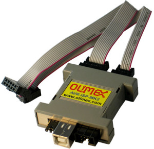
Though the standard programming header for xmega boards has 6 pins, they don’t use the AVR ISP method for interacting with the chip and burning new firmware. Xmegas use PDI–a different pin layout and protocol–and you need a compatible programmer. The Atmel AVR Dragon can handle the task, as can a few other programmers (I like the Olimex AVRISPmkII, which is good and inexpensive). There are also a few projects out there to build your own PDI programmer, like this one.
Once you have the programmer in hand, getting the firmware uploaded is pretty easy as you can just use your regular tools. I use avrdude, and a typical command line instruction using the Olimex looks like:
$ avrdude -c avrispmkII -P usb -p x128a4u -U flash:w:myprogram.hex
under Linux.
Using Xmegaduino
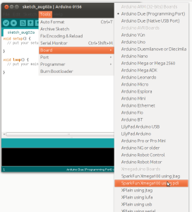
Getting Xmegaduino up and running with a compatible board is dead simple. Get the contents of the project from here, find the “arduino” executable within and start it up. You’ll see the familiar Arduino interface with a new section under Tools -> Board labelled “Xmegaduino Boards”. If you’ve got one of the boards listed, just select it and program as usual!
In cases where you have a different development board, or a designing your own, a little more work is involved. In short, you need to
- create a variant; and
- described the board for the IDE
Creating the variant involves adding a subdirectory to Xmegaduino/hardware/arduino/xmega/variants. Within, you’ll have two files: pins_arduino.h and serial_init.inc. Going over how to create these is beyond the scope of this intro, but in essence the trick is to base your variant on one of the existing boards and adjust the contents of the two files accordingly. Create a directory with a relevant name (“myboard”) in the same location, copy the two files over and edit. It’s not that hard, I’ve done it a number of times, but there is some figuring out involved.
Then, if you want to use the Arduino IDE to code, you’ll also need to add a section for your board in boards.txt. Find the file under the Xmegaduino installation directory and open it up. You’ll see an entry like
akafuino.name=Akafuino X

akafuino.build.mcu=atxmega32a4
akafuino.build.f_cpu=32000000L
akafuino.build.core=xmega
akafuino.build.variant=akafuino

... etc.
Copy the section that most closely resembles your own board, and change the variables accordingly, e.g.
myboard.name=My Super XMEGA board
myboard.build.mcu=atxmega128a4u
myboard.build.f_cpu=32000000L
myboard.build.core=xmega
myboard.build.variant=myboard
... etc.
Most of the time, I prefer to skip using the Arduino IDE altogether and just leverage the Xmegaduino SDK with a little Makefile to handle compiling and linking the build (I’m a fan of the command line, and it lets me use Eclipse or whatever IDE I like).
Wrapping up
So far, I’ve used the xmega family in 3 products and a host of smaller projects. They’ve proven to be powerful little beasts with a range of different uses, and they do it while being cheap both in terms of power requirements and actual cost-per-chip.
If you’ve felt constrained by your Arduino (I/O, serial lines, etc), or want to get access to more advanced features (hardware crypto, CRC, DMA), you should take a look at these microprocessors and the Xmegaduino project. Good luck and have fun!
