So it’s the middle of the night and I find myself in a jam… hm, a lot of my stories seem to start that way. Anyhow, it’s the middle of the night and I’m badly stuck: I need to talk with a two-wire chip I have on a breakout, but the I²C communication lines need to be pulled up to Vcc… but it’s surface-mount land around here, and I’ve got 0 through-hole resistors on hand!
Think, think… well, the biggest resistors I have are 1206. Not exactly breadboard material, but I figure I can solder some wires to a couple and get the job done. But it’s not pretty… it’ll be tough to do and ugly and brittle…
Illumination!
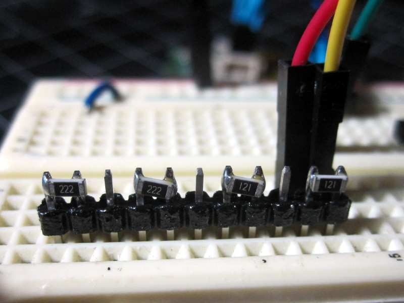
The 1206 components are 3.2 mm wide… a standard header is the same as the breadboard spacing, i.e. 100mil or 2.54mm… I went a little strong with the heat gun, but here is the result:
Aaaah! By leaving a pin between each resistor, I got a very usable row of pullups. Here I used two 2.2k resistors and, while I was at it, put in a couple of 120Ω for just-in-case.
It wasn’t my best work, but it sure did the job and I’m really liking the form factor. I think I’m going to make a couple more as it’s a lot cleaner than having a bunch of long-legged resistors everywhere on my breadboard.
EDIT: So I did a little search and, unsurprisingly, I’m not the first to invent this method… but I sure wish I’d known about it before so I’ll leave this here in the hopes of spreading the word on this neat (both literally and figuratively) little hack.
