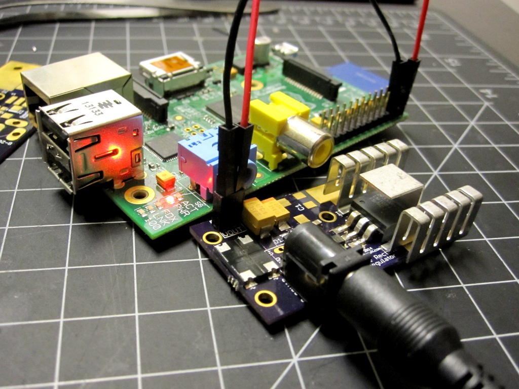
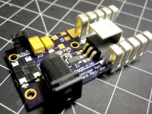
Needing a modular power supply that could handle a few amps and both AC and DC input, I recently designed a circuit to perform the task. Here I’ll go over the main points and a few lessons learned.
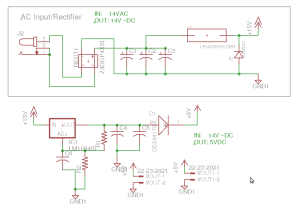
The circuit itself is nothing very complicated.
Just a rectifier feeding into some smoothing caps, whose output is then fed to an adjustable voltage regulator (an LM1084). I included a zener diode to clamp anything extreme before it hit the regulator, and a placeholder for an eventual inductor and a diode on the output to make sure nothing I attach to the module feeds back into the regulator.
The reason an adjustable regulator was used, rather than just going with an LM1084-5.0, was both to allow more flexibility later (by changing the resistors in the adjustment feedback network) and because I wanted to ensure 5V got through even after the forward voltage drop due to the barrier diode. The idea was simply to adjust the output to account for the drop, so e.g. output 5.5V and drop 0.5 in the diode.
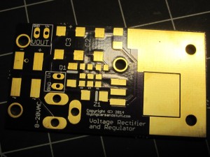
On the resulting PCB, thick traces (24mil) were used for everything that would carry current. I left room for 3 filtering capacitors, to give me room to handle excess ripple on certain AC sources and because high capacitance parts that can handle high voltage get expensive quickly–thought I could get away by putting smaller values in parallel to get as much C in the end. I also tried to leave ample room for sinking heat away from the board–if I was lucky without a heatsink but, worst case, having enough room to add one.
The finished module does it’s job pretty well. However, should I redo it, here’s what I would do differently.
Low forward voltage drop
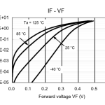 I didn’t pay enough attention to the barrier diode’s forward voltage drop curve, and just built the module with worst case in mind. When the load is small and/or the temperature is high, this voltage drop is much lower than the ~0.5V I set things up for. This means that, using a 499/147 ohm network, my output voltage is a bit too high most of the time. Not such a big deal, since I can adjust the output using different resistors, but it would be nice to have something more stable over a greater range of use cases (i.e. both high and low current draws). I’m going to have to research this a bit in the future.
Greater isolation of on-board heat-sink: I only used 10mil isolation on the heat sink polygon, and it’s easy to cause a bridge while soldering on the heatsink proper. Because the LM1084 tab is tied to the output, this makes the whole heatsink a path for shorts. Not so good.
Better heat sink: it gets pretty hot when stepping down from a high voltage, and my cheapish 7109DG heatsinks have trouble doing the job without a lot of airflow.
1206 parts: I used 0805 parts when I could’ve used 1206 without making the board any larger. Using 0805 makes building it by hand harder than it needs to be.
Rectifier overkill: it’s good to design conservatively, but the rectifier used can handle 600V–which might, just might, destroy the rest of the components… I think I’ll go with something smaller next time.
Finally, the LM1084 can provide lots of power but as mentioned it runs pretty hot. A better heat sink, good air flow and using a supply that’s just high enough to get by the rectifier and provide enough overhead for the regulator will all help in this regard. In this case, assuming we want to output 5.5V, the 5.5 + 1.5V (dropout) + 1.2 V (rectifier total forward voltage) = 8V and a bit. So a 9V supply is probably best, though it should easily handle 25V (adjusting the zener diode accordingly).
Hopefully this little post-mortem of my rectifier/regulator design will help you while building your own particular solutions. Don’t hesitate to write if you have comments or questions.
Cheers.
