If you’ve gone over the outline and schematics, it’s time to go over the main steps involved in the actual construction of ACID.
Materials
The project is split into three components:
- an Ardweeny
- a small TCS3200 control module, which may be used on its own
- a main board, which holds everything together along with supporting components
Tools
At a minimum, you’ll need a soldering iron, solder, solder flux, a drill and small bits. A multimeter is mighty helpful. If you’ll be etching your own PCBs, you’ll need boards, etching solutions and any other materials required by the selected technique.
Parts
In addition to the Ardweeny kit, an FTDI programmer for it, the two printed circuit boards (which may be etched using the provided files, contact me if interested in purchasing), and a bit of wire for the two jumpers, the components required are listed below.
TCS3200 Control Module
| ID | Type | Value |
| C1 | Capacitor | 1uF |
| IC1 | SMT Sensor | TCS3200 |
| LED1,LED2 | LED | 5mm bright white LED |
| R1 | Resistor | 2.2k |
| R2, R3 | Resistor | 100 |
| T1 | Transistor | 2N3904 |
| SV1 | Header | SIP 8-pin female |
Main Board
| ID | Type | Value |
| C1, C2, C3, C7, CS1, CS2, CS3 | Capacitor | 1 uF |
| C4, C6 | Capacitor | 10 uF |
| C5 | Capacitor | 100 nF |
| CS5 | Capacitor | 220 uF |
| DP1 | Digital Potentiometer | MCP4151 |
| IC1 | Socket | DIL28-3 28 pin socket for Ardweeny |
| IC2 | Hex Schmitt-trigger inverter | 7414N |
| IC3, IC4 | Single-supply dual op-amp | TLV4112 |
| IC5 | Voltage regulator | 7805 or similar, in TO-220 |
| R1 | Resistor | 100k |
| RC1 | Resistor | 1k |
| RC2 | Resistor | 470 |
| RC3 | Resistor | 220 |
| RS1, RS2 | Resistor | 10k |
| RS3 | Resistor | 5.1k |
| RS4 | Resistor | 200 |
| SW1, SW2 | Switch | N-O momentary contact |
| SPIOUT | Header | SIL 3-pin female |
| TCS3200 | Header | SIL 8-pin 90-degree male |
| POWER | Header | SIL 4-pin female |
| CALIBMOM | Header | SIL 2-pin female |
Miscellaneous
| Type | Value |
| Filter | High Transmittance IR Filter |
| Lens | Convex condenser lens |
| Speaker | An 8-ohm speaker that fits in your enclosure |
| Pins | Male SIL pins, to plug into those female (switch, power…) headers |
Files
You’ll need the files in the ACID resource package, from download page.
With everything in hand, we can get down to building the device!
PCBs
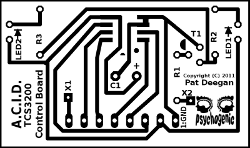
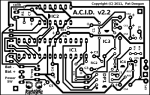
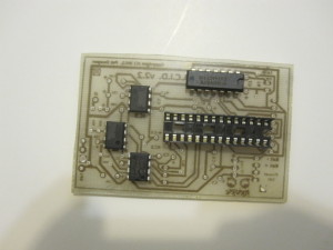
If, like me, you are rolling your own printed circuit boards you need only transfer the provided masks to your boards and etch them as usual. There are numerous resources online that describe the process you’ll find one article I like on the toner transfer method here ;-)
Note: Do NOT try to use these images to make your printed circuit boards (they are low res)–download the package and use the PNG files within (which are at 600dpi).
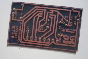
You can see that, since these are single-sided boards, I add a good deal of information that comes in handy while the PCB is being populated right on the side with the trace.
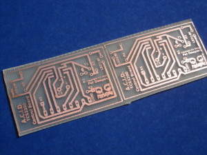
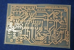
Here are some results of the toner transfer and etching of the TCS module and main board.
The most important things to check for at this stage are interrupted traces and contact bridges between adjacent copper lines. A multimeter in continuity (“beep”) mode is a real help here. I don’t usually have to deal with many broken paths, as I make certain I avoid over-etching. The cost of this is needing to use an exacto to sever a few extraneous contact points (still much easier than attempting to fill trace gaps on a PCB).
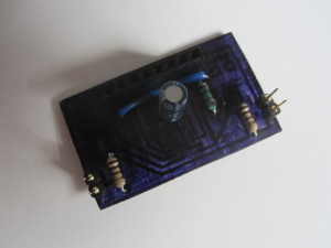
I coloured the back of the TCS module, ’cause it looks cool.
Ardweeny
Begin by building the Ardweeny as specified by the included instructions. I didn’t solder on the green LED, to avoid having a light source within the enclosure, and trimmed the programming header pins to half their length without ill-effect (be careful here, to ensure your FTDI-cable/programmer can still contact the pins, though).
TCS3200 Control Module
The TCS3200 board has few parts and is straightforward, but for a single challenge: the TCS3200 chip itself.
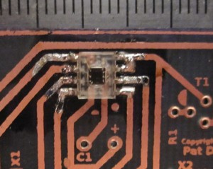
Being a surface mount component, the TCS3200 will be placed on the underside of the board directly atop the copper trace. There are guides available online about soldering SMT components by hand, but the gist of it all is this: flux!
Using a sticky, resinous, solder flux applied liberally to the pads, gently position the part so it is perfectly centered. Make certain you get the orientation correct. Notice that one, much larger, lead with a different “L” shape through the transparent chip? That’s pin 4 (GND), and it must be in the upper right corner, when facing the copper side. You’ll notice that it is tied to pin 3 (below it, from this point of view) by the PCB. That is a good thing.
Use tweezers to hold the TCS3200 in place and get ready to handle your soldering iron. Now you break all the rules and apply a bit of solder directly to your iron–less is more, here, avoid gobs–and touch the tip to the joint between one of the chips corner legs and a pad. The solder will flow and wet the joint by capillary action. If you’ve got a lot of solder, drag the tip along the trace and it will leave a trail on the copper.
Remove the iron and give the solder a moment to cool. If the chip is still correctly aligned, proceed in a similar fashion with the opposite corner and then to the six remaining pads.
Probe the connections between the header pads and the chip’s leads using a multimeter. Take a break when you hear a beep on each one and bask in the knowledge that you can now handle SMT components.
Add the rest of the components and don’t forget to add a jumper, by soldering a wire between the X1 and X2 pads.
IR Filter
As mentioned above, the TCS3200 is sensitive to interference from infrared light. Though IR filters can be rather expensive, we only need a piece as large as the TCS3200, and it is possible to find many suppliers online that will provide something suitable. A search for “High transmittance Glass IR Filter Lens” usually yields many interesting results, or you may be able purchase some from here.
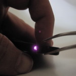
The easiest way to test your filter is with a digital camera and remote control. If the camera picks up the light emitted by the LED on the remote, it will be able to show you that the filter is blocking IR just by placing it between the LED and camera.
Having found a functional piece of filter glass, I simply placed it atop the TCS3200 and applied a few gobs of hot glue around the perimeter to secure it permanently.
Main Board
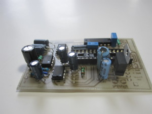
Other than having a good number of holes to drill, the mainboard presents little difficulty. Begin with the 28 pin socket for the Ardweeny, and the four ICs.
Next come the resistors, capacitors, voltage regulator and headers. Finally, a jumper must be soldered between pads J1 and J2.
Assembly
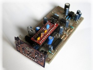
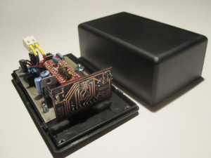
Place the Ardweeny in the socket, slide the TCS3200 module onto the header at the front of the mainboard, and admire your work.
Lens
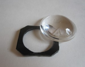
To maximize ACID’s efficacy, you’ll need to place a condenser lens before the TCS3200 chip so that it’s focal point is aimed at the photoreceptors. Almost any lens will do, it can be from a magnifying glass or one of the cheap “High Power LED convex lens” found online. The choice of lens is a trade-off between power and precision (a large fish eye lens will provide lots of light but it will be hard to target specific objects). A lens with one flat side will be easier to install.
You can determine the focal length of any lens just by focusing a distant light source on a wall or sheet of paper. Measure the distance between the lens and the surface when the focus is about perfect. That will be the amount of free space you’ll need between the TCS3200 and the lens, in your enclosure. I didn’t have quite enough space in my box, so I created a little shim to set the lens on before gluing it to the box.
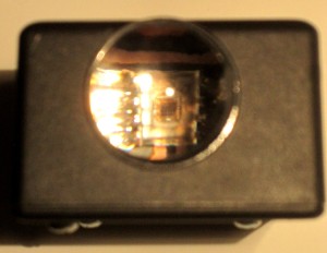
If you can see the chip through the lens when you are looking at it dead-on, you’ve done a good job.
Enclosure
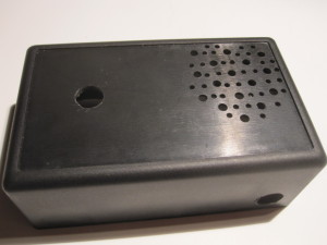
After ensuring I could fit everything into my little black box, I used bolts to secure the board to the base and drilled holes for the viewport lens, switches and speaker output in the cover.
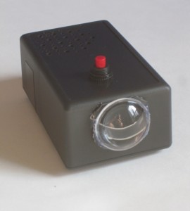
After that, it’s just a matter of attaching the lens, stuffing everything inside and… voila!
Programming
If you don’t already have the arduino IDE and its TimerOne library installed, set them both up.
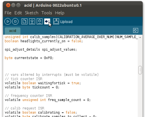
Remove the Ardweeny from the main board, plug in the FTDI programmer and launch the arduino IDE. Set it to “Arduino Duemilanove w/ ATmega328”, load the ACID.ino sketch, compile and upload it using the button with the arrow pointing to the right.
The Ardweeny should now be ready to perform its colour-converting task. Pop it back into place, hookup the battery and press the power switch.
Project Pages
ACID Overview
[siblings]
