I loooove LEDs: they’re easy to use and really efficient. I’ve always wanted to use light-emitting diodes to feed, or at least supplement, my plants because you can get a lot of lumen without using many Watts and also because you can target the frequencies usable by chlorophyll (in the red and blue parts of the spectrum–which is why leaves are green, being the sum of the light that’s rejected by the plant).
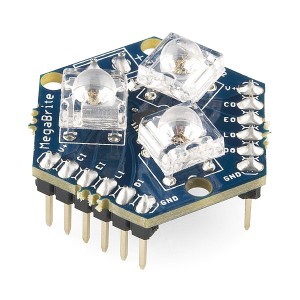
I’ve found that the MegaBrite, a neat little component that handles all the hardest parts of powerful RGB lighting for you, is perfect for this and will present my first impressions here.
Tricky Parts

© Espion | Dreamstime Stock Photos & Stock Free Images
The main problems with LED lighting for my flora so far have been:
- LEDs are really efficient but they’re usually low brightness (compared to a lightbulb), so you need *lotsa*
- If you just apply a potential across the leads, current will rush through until the LED’s magic smoke escapes and it is rendered inoperative
- LEDs are pretty much binary, i.e. on or off and there’s hardly any middle ground and thus no room for dimming illumination.
High-powered versions are now available that are much brighter than standard LEDs, which helps reduce the part count.
The problem of current control is a bit trickier. In a standard configuration, you’ll just put a resistor in line with the diode to limit the current. This is fine when the LED is consuming a mere 30mA. However, when we’re talking about a bunch of high powered LEDs eating up, say, a total of 2 Amps, those resistors will start heating up and disippating a lot of power for nothing. That’s not only inelegant: it requires big resistors and measures to get rid of all that waste heat… a total drag.
A better solution is to control the current at the source in a cleaner way, i.e. using an active current limiter (see a simple example here). This allows you to feed the current directly to your LEDs, reducing the number of resistors and the amount of waste at the cost of adding a few active components and a bit more complexity.
As for dimming, the standard solution is to use pulse-width modulation (PWM): quickly sending a stream of rapid on-off pulses, faster than the human eye can process. By varying the amount of time the LED is on versus off, we can achieve attenuation of the lighting from completely off through to full on.
With microcontrollers like the AVR (on which Arduinos are based), PWM is very easy. Still, to support many LEDs of differing frequencies (e.g. an RGB setup), you’ll either need lots of PWM-enabled outputs or 3 PWM outputs and circuitry to support sharing these command/current source signals between multiple LEDs (since the pins or an AVR can only handle small amounts of output current).
A simpler solution
Fortunately, there are components available that handle all of the above for you. One in particular, that I’ve been playing around with and am enjoying greatly, is the MegaBrite.

The MegaBrite, from Macetech
MegaBrites are a combination of 3 sets of LEDs. Each set is equivalent to 15 standard LEDs of one of red, green or blue. Also on-board is an A6281 (Allegro 3-Channel Constant Current LED Driver with Programmable PWM Control).
From the outside, the MegaBrite looks like a single, programmable, RGB LED. You can specify the intensity for each of red, green and blue with 10-bit resolution (a value between 0 and 1023).
Best of all, the MegaBrites are designed to be easily daisy-chained. This means that, using three or four pins on your microcontroller, you can control (almost) any number of MegaBrites with no additional components (other than wiring between all the components). Now that’s easy :)
Programming
Telling the MegaBrite (or it’s siblings the ShiftBrite and ShiftBar) how to behave is simply a matter of sending the settings you want over SPI (or even bit-banged), packaged as a 32-bit integer. There are details on this on the product documentation page.
When you want to control a number of *Brites, you tie the first one to your micro-controller and then daisy-chain them–tying the outputs of the first to the inputs on the second, etc. Each 32-bit command gets pushed down the chain, such that if you have 4 of the components tied together you simply send 4×32 bits. This allows you to configure each device independently, but means that if you only want to change the settings on one of them, you’re still going to have to send the 4 commands.
A latch is used to tell the entire chain when you’re done sending control bits, which keeps the modules from going wild while the bit-train is in an inconsistent state (i.e. while you’re still pumping bits down the line).
Conclusion
So far, I’ve really enjoyed playing with these RGB LEDs. I find the form-factor a little weird but since I’ll be chaining them together using ribbon cable or the like, rather than putting them on a PCB, it doesn’t really matter.
I’m still working on my little illumination system, but will be presenting the results here as soon as it’s ready.